Seagate Dockstar: Add an accessible serial port
by firestorm_v1 on Jul.21, 2010, under Embedded devices, Hardware, How-To's

Ok, so not long after I published the article on the hardware teardown of the Seagate Dockstar, I couldn’t help myself so I started working on things to do with this device. I did a lot of research in regards to the capabilities of the Dockstar, including being able to push a customized Linux OS on the device. Once I saw the article at Hackaday that covers exactly how to replace the OS, I knew I had to do it for myself. There are two ways to perform this upgrade however in order to capture syslog output and to be able to get to the bootloader, a serial port is required. Just about all of the sites will describe the pins needed to make the connection, however none of them detail how to do it very clearly and none of them address the issue of aesthetics. Read on for my method of adding a serial port to the Dockstar without affecting the look of the device.
Before We Begin….
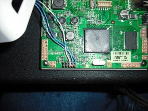
The Seagate Dockstar has a serial port available via three of the pins on the header at the front of the PCB. The issue is that they’re not very easy to get to without having to disassemble the device each and every time you need to do a recovery on it. This is hardly an ideal solution, and who knows what I’ll be doing with the device in the future. If I decide to embed the device and something goes wrong, I’ll have to have access to the serial port in order to debug it.
But, simply having access to the serial port is not enough. The Dockstar’s aesthetic elegance is in the fact that it’s so simple. No massive amount of connectors aside from Power and Ethernet, and with little room to begin with, I don’t want to have a cable hanging out of the box just to have access to the serial port. After much deliberation, I decided that a pin-row setup would be ideal instead of some other outward-facing connector. The advantages to a pin-row set up is that there are only as many holes as are needed to establish connection and the connector size is significantly smaller than would be a standard DB-9 connector. An additional advantage to the pin-row setup is that the connection would be temporary and can be easily removed. The resulting connection port would still be cleanly presented and would not stick out like a sore thumb.
Parts List:
In order to pull this off, you will need the following items:
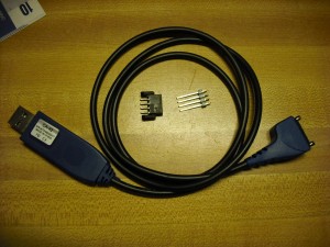
– a CA-42 USB cable. – This is most commonly sold as a Nokia cable through Amazon and can usually be had for a few bucks. This is required as the dockstar’s serial port voltages are at a 3.3V TTL. interfacing it to a standard +12V/-12V serial port will damage your Dockstar. The CA-42 cable has a PL-2303 USB to 3.3v TTL serial adapter in it which provides the required 3.3v TTL and gives an easy to use connector for plugging it into your host PC.
– a 4-pin header with long pins. – The pins have to be long enough that they will go through the Dockstar case and into the matched connector securely.
– a matched connector for the 4 pin header. – This will be mounted inside the Dockstar.
– Heat shrink tubing of various sizes. (Use the images as a guide)
– A couple of spares of the 4 pin header and the connector. (We’ll use one spare for making the holes in the case, but it’s always good to have extras just in case.
Tools List:
– Soldering Iron
– Lighter (for heatshrink)
– small diameter drillbits
– Spudger (or Radio Shack soldering toolkit)
– A Linux machine with an available USB port. Note: It may be possible to use a windows computer for testing however my USB adapter only works in Linux.
Now that you have all the components, it’s important to stop here for a sec and cover the legal mess. It is critically important that you know what you’re doing. You can not blame me or hold this site responsible (or the maintainers of this site) if you do something and blow up your Dockstar. Be careful, do your research, check twice, solder once.
Please note that if you have never worked with shrinkwrap, the important thing is to watch the fire and keep it moving. If you leave the lighter in the same place for too long, the shrinkwrap will stop shrinking and will catch fire. When in doubt, apply the hat quickly and watch the shrinkwrap closely. If it does something wrong, move the lighter away and start blowing on it to cool it down.
Part 1: The Cable
It’s easier to do the modification on the cable first rather than do the Dockstar portion due to the fact that part of performing the Dockstar side of things will require testing to make sure it’s all working properly. So, let’s get started.
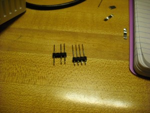
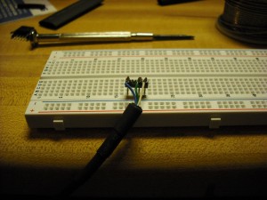
This is the cable that we will be hacking together. The pin-row connector shown above is a 4 pin wirewrap terminal and a push-on style PCB mount connector.
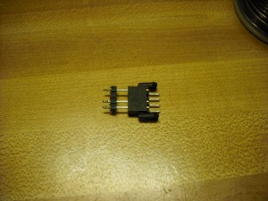
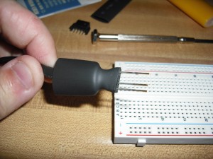
In the above photo,you can see the long header pins and the matching connector and how they fit together. Before we get started with modifying the cable, we first need to figure out how it’s wired up. Because there is a very good chance that you have a generic cable, and generic cables are wired differently, we will start off with spudging the USB connector apart.
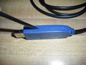
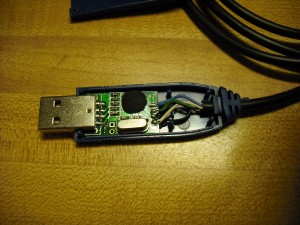
Follow the plastic seam of the USB connector with the sharp blade of the spudger. Gently work the two halves of the plastic apart until you are able to seperate them. You should see a connector that looks like the one below.
A closer of the PCB will reveal that the wires (white, blue and green) are labeled for our easy hacking convenience . The three wires in my cable are Blue(GND), Green (RxD), and White (TxD). Now that we know which wire does what, reassemble the USB cable as we will not need to do any work on this end of the cable. Starting with the 4 pin connector, pick one of the two internal pins and remove it.
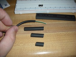
The reason for removing the offset pin is for two reasons. 1) There are only three wires required for connection and 2) The missing pin will allow us to key the connector so that it can’t be reversed. Going back to the USB cable, cut off the fat Nokia phone end and strip the cable back about an inch. To help with soldering, insert the long end of the header pins into a block of breadboard. This will help hold the connection stable while you solder the cable. You will also need to cut the small diameter shrinkwrap in three sizes as shown below.
The reason for the three lengths of heatshrink tubing is that we will build up the edge of the cable to a large size so that we can use the larger heatshrink tube (in the back of the picture) to bind the header pins into the wrap and the wrap to the end of the cable to strengthen the cable. If you have never worked with heatshrink tubing, it’s very easy to work with. Start with the longest piece of tubing, and slide it over the cable. Make sure that the cut end matches the end of the insulation and heat with the lighter. KEEP THE FLAME MOVING ACROSS THE HEATSHRINK!! Once the heatshrink has stopped shrinking, allow it to cool and repeat for each piece.
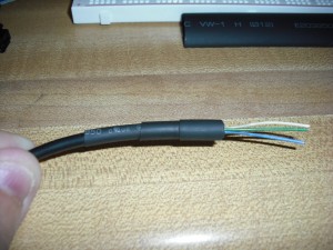
This is the end result of the shrinkwrapping. Now that the end is built up, slide a piece of the large shrink over the end of the cable but do not apply heat just yet. Strip back the individual wires so that you can attach them to the header pins.
Now that we’re ready to solder the connector, it’s important to decide how to create the pinout. In my setup, I elected to have the GND connection by itself, then the TX and RX pins. For each wire, wrap the wire around the soldering post on the header pins and solder. Be sure to use only enough solder as is required for the connection and do not bridge the pins.
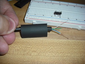
Now with the cable soldered and the connections solid, it’s time to apply the heat to the large heatshrink. Very carefully pull the end of the heatshrink over the black plastic header and gently apply heat. Adjust if needed and let the tubing shrink without it pulling itself off of the header plastic.
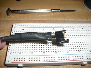
When you have it this far, go ahead and apply heat to the rest of the heatshrink tubing, making sure not to singe it. When you are done, you should have a cable looking like the one below.
This was the easy part, Now it’s time for the dockstar.
Part 2: The Dockstar
We’ve got the cable, but without something to connect it to, it’s pretty useless (unless you want to use it on a breadboard). Let’s take a look at what’s going on.
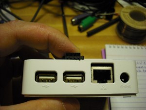
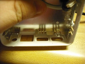
Since I’ve already determined that I want the connector for the serial to come out of the back of the device and I’ve already found a suitably small connector, it’s time to find a location where I can attach it without getting too involved or without interfering with the existing ports on the back of the dockstar. I’ve elected to put the serial port just above the center USB connector. In the photo above, you can see how much space we’re dealing with in comparison with the USB ports and the header socket.
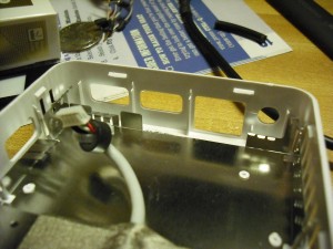
Some of the RF shielding will need to be removed, but thankfully the metal is pretty flimsy and easily cut. Be sure that when you remove the little fins pictured that you do not distort the top of the metal shielding. We need a surface as smooth as possible for the superglue to properly bind with the connector for the serial port.
Here is the picture of the unneeded shielding removed. Please only remove the shielding that you need. Next, you will need to prep another three pin header just like you did for the cable. Rather than trusting faulty measurements and guessing, we’re going to use the header’s pins themselves to point out where we need to place our holes.
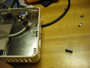
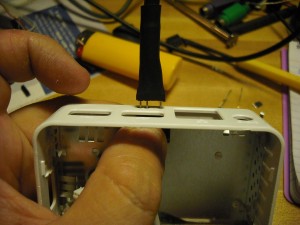
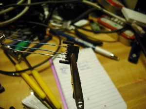
Using a pair of needlenose pliers and your soldering iron, heat the pins evenly and apply moderate pressure. The pins may wiggle slightly but don’t let them move too far off otherwise your holes won’t be lined up. When all three pins have punched through, remove the pins with the needlenose pliers. Use the small diameter drill bit to widen the holes and to furr out any residual plastic scraps. Your finished holes should look something like below.
Just to make absolutely sure, go ahead and test with the connector and the cable to make sure everything fits properly.
If you’ve made it this far, you’re doing good. Now it’s time to prep the connector for supergluing into the Dockstar’s case. Since it’s a four pin connector and we’re only using three pins, make sure that the connector is properly oriented so that it fits properly and so that the serial cable can move freely in and out of the connector. Back the cable off a bit so you can see which pin is missing and cut off the connector’s matching pin to eliminate a possible mis-wiring later on. Go ahead and attach and solder a wire to each of the three remaining pins.
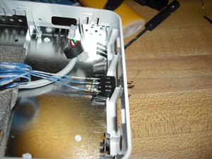
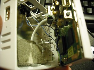
In order to glue the connector socket in, take the excess wire and coil it up for now. Apply a thin coat of superglue inside the Dockstar and when aligned, push the three pin header you used for burning the connector in through your drilled holes and into the connector. This will hold the socket steady while the superglue cures. Give it about 15 minutes to cure properly, then gently remove the pins from the socket. At this point, you should have a fully mounted socket like in the picture below.
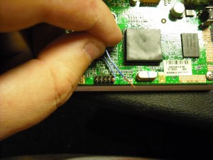
Now that the socket is taken care of, we need to attach it to the serial port on the Dockstar’s board. Before we do anything permanent, we will test the serial port and then once we are satisfied that it’s all working, we’ll solder them in and close it up. Start off with wrapping the ground wire to the lower right hand pin on the connection block. This is the common GND connection and must be established first. If you are using my wiring plan, the GND wire is the single pin by itself on the three pin header we made earlier.
The two pins to the left of the GND pin are the RX and TX pins respectively. Attach the centermost pin to RX and the remaining pin to TX on the superglued connector.
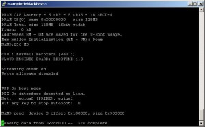
Remember, we have NOT soldered the three wires yet. Also, make sure that none of the wires are touching prior to connection. In order to test the serial port and make sure we have it hooked up right, connect the three pin header on the serial cable to your socket on the back of the Dockstar and connect the USB connector to your computer. Do not apply power to the Dockstar yet. Open up minicom and set the serial device to /dev/ttyUSB0, 115200, no parity, 8 bits, 1 stop bit. When properly configured, apply power to the Dockstar and watch your console window. If you got it right, you should get similar output like below. If not, pull the power plug on the Dockstar and disconenct the serial cable out of the back of the dockstar. Swap the left two pins (RX and TX) and try again. You should get output like below.
Now that you’ve tested the wiring, disconnect the power and the serial cable from the Dockstar. Solder the wires in place and reassemble the Dockstar. Be careful closing the cover as you want to make sure that the wires coming off the superglued socket do not touch the metal shielding. (Editor’s Note: I really need a hot glue gun)
Close it all up and test it one more time. If everything works as should, you’re good to go. Now you can access the serial port without having to take your Dockstar apart over and over again.
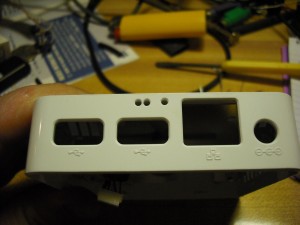
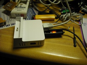
Here is a picture of the completed serial cable mod. The serial cable is plugged in right above the keydrive in this photo.
Same view as above, but with the serial cable removed. Nothing but three holes.
36 Comments for this entry
7 Trackbacks / Pingbacks for this entry
-
Adding a serial port to a Dockstar - Hack a Day
July 22nd, 2010 on 10:03 am[…] condition. But look at the three holes in the white case just above the thumb drive which act as a serial connection for the Dockstar. [Firestorm_v1] posted the instructions after see our post about installing OpenWRT on the device. […]
-
onderka.com » Eintrag » Seagate Dockstar Kernel 2.6.33.5
August 22nd, 2010 on 3:04 am[…] Linux-System zur Hand habt, auf dem Ihr den “original”-Kernel umkopieren könnt) die Serielle Schnittstelle mit einem Nokia CA-42 Kabel […]
-
Seagate Dockstar Discussion and Tutorial Thread
August 26th, 2010 on 2:51 am[…] please man! Sorry man, I dont have a good cam, my phone camera sucks. You can check this post, I didn't use any of the connectors which he used, just manually wrapped the wires around the pins […]
-
Seagate Dockstar | Rebells Blog
August 28th, 2010 on 8:15 am[…] -LCD2USB -diverse V-USB Projekte wie z.B. PowerSwitch -ein Kabel um bei einer misslungenen Konfiguration die Dockstar zu […]
-
Matzes Bastelbude » Seagate Dockstar mit OpenWRT
October 3rd, 2010 on 7:48 am[…] paar Bilder dazu findet man auch hier http://www.yourwarrantyisvoid.com/2010/07/21/seagate-dockstar-add-an-accessible-serial-port/ Die serielle Schnittstelle hat 3,3V Pegel. Wenn man also mit einem normalen RS232 mit 5V arbeitet […]
-
Jouer avec les diodes de son DockStar | Linux-backtrack.com
February 6th, 2011 on 9:16 pm[…] fallu réinvestir dans un fer à souder et autres accessoires de bricolage pour faire un adaptateur USB-série pour récupérer le bootloader que j’avais réussi à bricker. Toujours est-il que je me suis […]
-
IP Camera Hardware List | My Blog
March 17th, 2011 on 9:16 am[…] to the Dockstar, a really good guide on adding a serial header to the device can be found here : http://www.yourwarrantyisvoid.com/2010/07/21/seagate-dockstar-add-an-accessible-serial-port/ Highly recommended read. As a result I wont go into this unless I get […]
July 22nd, 2010 on 2:03 pm
Why on earth do you want a serial port on a dockstar?
July 22nd, 2010 on 7:16 pm
Just to be pedantic about it, the PL2303 is a USB-Serial adapter. It is not a level shifter, and does not do any level shifting. It also depends on how the chip is wired (And yours is the first I’ve seen as a cob). One of the pins adjusts the voltage of the rx and tx lines from 5v, to 3.3 to 3, depending on the input voltage (for older chips).
Have you measured the actual voltage levels of yours?
July 23rd, 2010 on 11:27 am
Nicely done! I’ll be doing this soon.
Comments: “Shrinkwrap” is like plastic food wrap; what you’re using is called heatshrink tubing. Instead of a lighter (difficult to control), use a hair dryer (which is essentially what an industrial heat gun is — see the Paladin 1873 on Newegg or http://www.heatgunstore.com). Start a few inches back and gradually move closer to keep from melting nearby parts. Why not use a removable 10-pin female socket to connect to the header?
July 26th, 2010 on 9:41 am
thank you for this documentation
I’ll soon be able to test a dockstar en OpenWrt.
July 29th, 2010 on 12:51 am
What about if you sacrifice the mini USB connector and use it for serial connector, then it is more clean (no small holes). Just cut it wire and solder to serial connetor pins. Inside the case, you can solder USB memory, USB bluetooth or USB wireless lan to the mini USB pins. Use CA-42 cable solder it to female mini USB then.
July 30th, 2010 on 8:57 pm
Very nice. It occurred to me that it might be possible to put the guts of the CA-42 *inside* the DockStar, and re-purpose the mini-USB connector (since its cable can be easily disconnected). What do you think?
August 10th, 2010 on 1:53 am
To avoid cutting open the USB connector, I guess you can use a multimeter (Ohm) to find the GND cable (from pin 4 on the USB connector), then trial and error like already described to figure out RX and TX.
August 10th, 2010 on 11:30 am
Hey Everyone, sorry for the long wait getting back to you all. I’ve got a bunch of stuff going on in life which has definitely hampered my responsiveness but I didn’t forget about you all!
@Ben:
The reason why a serial port on the Dockstar is a good idea is so that you can get access to the bootloader and flash or TFTP in your own images for use. While there are some instructions online for replacing the stock kernel and rootfs with a custom-rolled distribution, they will invariably require access to the serial port to issue commands to the bootloader.
@cde:
You’re right, it’s a USB-TTL adapter, not a level shifter. When I measured my voltages it was inline with what I expected, usually around 3.3v with a .2v delta. It was pretty stable at 3.3v and since this article was posted, it has not given me any issues whatsoever. I’ve updated the article and changed it from level shifter to “USB to 3.3V TTL adapter” to prevent any miscommunication. Thanks for the tip.
@Richard M.:
I’ve been debating on getting a heat gun for a while and have tried the hair dryer approach without much success. Unfortunately, I don’t think the hair dryer I have on hand is strong enough to get the heatshrink tubing to shrink. I’ve updated the article to indicate heatshrink tubing instead of shrinkwrap. Thank you for the tip.
@Loc N:
I thought about using that USB port for the serial connection however I was wanting to keep that connector stock just in case I do get my hands on a Seagate FreeAgent USB drive (or at least a case). For the time being, I have a USB Mini to USB A female adapter currently hosting a keydrive.
@Eric C:
That was another approach I was thinking about when I set out to add the serial port to the Dockstar however my concern was adding extra hardware to an already cramped form factor may adversely impact the device’s performance and cooling. I may ultimately end up going that direction later on however the
@Tormod:
You’re right, opening the USB cable wasn’t a total requirement, and the only reason I did it was because I wanted to ensure there weren’t any surprises or additional control lines that needed to be dealt with. The guy that gave me the cable said that his cable had five wires (TX, RX, DSR, DTR and GND) despite his cable and my cable being marked and sold with identical part numbers.
I want to thank you all for taking the time to comment on my article. As soon as life calms down, I anticipate doing a followup on the Dockstar and outline the interesting experiences I’ve encountered with trying to get a usable OS on the device.
August 18th, 2010 on 6:17 pm
It’s not TTL, either, if it will trigger on 3.3v. TTL is +5V logic, now we use various types of CMOS which trigger (depending on feature size) on voltages which can be small fractions of a volt. Old CMOS stuff took about 2.5V to trigger reliably and was usually used closer to 3V. All these numbers are made up except +5V for TTL, because CMOS doesn’t have a single voltage.
Thanks for your article! Adding serial to my dockstar right now.
August 25th, 2010 on 5:53 am
Would it be a problem if instead of the 4-pin connector one uses a 3-pin stereo connector?
September 1st, 2010 on 10:21 pm
Just tried this hack and when I hook the USB to the computer and open minicom it goes nuts, and keeps pushing out gibberish even with the dockstar unplugged. When I plug it in the gibberish just keeps scrolling. I am not quite sure but I think my dockstar is bricked, but even if it is I shouldn’t be getting gibberish when the dockstar isn’t plugged in. Any ideas?
September 2nd, 2010 on 1:11 pm
@Martin E:
You are correct. Unfortunately in the EE world, I’m only a couple steps above total n00b so I wasn’t sure what the terminology was. I knew it wasn’t RS232 because that’s typically a +12/-12 power level, and had heard about TTL being +5v in working with some mocrocontroller projects I was working with.
I hope your serial port works fine for you! Enjoy your modded Dockstar and look for an article coming up soon in regards to the rest of the pins on that header!
@SupremeDalek:
I don’t think there would be a problem with it. I didn’t have much clearance and when I went to EPO to get parts, I was limited to what they had on hand.
@laptopfreek0
That’s a good question. I did notice that when my CA42 cable was not connected to the Dockstar, minicom would start spouting random gibberish like you said. Based on that, it sounds like your GND wire may not be connected properly and your RX wire has lost reference. Check the connections on your GND wire and your RX wire and you should be OK.
All:
The rest of the connections on that Dockstar are indeed a JTAG port. The guys over at Plugapps.com have found out which connections to make to a parallel JTAG in order to be able to recover from a failed flash. Since I’ve bricked my dockstar, I’m waiting on the JTAG cable to come in so I can learn how to do it and pass the knowledge on to you guys!
September 2nd, 2010 on 7:11 pm
I have a slight problem. After opening my usb serial cable I got off ebay I realized that it might not be the same pinout that you have. There is no markings that specify gnd, trx, or rcx. Attached is a photo… Got any clue what the pinout might be? Also it is the highest resolution that I could take.
http://picasaweb.google.com/lh/photo/r1JFQd46Qfj2TauwrVSmcj5RbMHi84n0KoDipkROSg4?feat=directlink
September 2nd, 2010 on 7:25 pm
Oh wait I figured it out… If anyone has one of the generic chinese cables bought off ebay this should help.
http://i47.tinypic.com/10z0da0.jpg
September 2nd, 2010 on 9:57 pm
@laptopfreek0
I’m glad you got it figured out. If you don’t mind, can I mirror that image to prevent picasa from delete it? That’s a real good image to have as these CA-42 cables are pretty common but can vary wildly in the internals.
September 11th, 2010 on 7:06 am
laptopfreek0, did you get the ebay cable to work?
September 21st, 2010 on 11:18 am
I got a CA-42 from amazon today and tested it right away. Mine got six internal wires. (Blue, Green, White and Yellow, Orange, Red). I clipped the last three after testing. They are not required. Everything else worked out just fine.
October 28th, 2010 on 10:53 am
Hi,
got two problems with my dockstar.
1. made the damn firmware update by mistake,
registered at Pogo, enabled SSH, edited rcs
for delete of update search at pogo.
So not telnet & ssh running on dockstar.
No ports open / listening.
Any help ??
2. Bought a cheap ca-42 cable. The usb side has a
heat-sealed cover that could not be open without
risking to damage the internal parts.
Next is that the cable just got 3 wires inside.
The colors of the wires are red, orange and blue.
Any ideas ??
November 16th, 2010 on 8:26 pm
Hey 0815_user:
As far as the firmware update, not sure. None of mine have seen Internet access prior to me updating their firmware with Debian. It’s possible that the upgrade did something and rendered the device inoperable. It’s a good thing you got that CA-42.
As far as finding the pinout on the CA-42, you can try a couple of things:
1) To find ground, get a voltmeter, set to continuity and then put one end on the silver part of the USB connector. Now find the pin (may be more) that gives you continuity (no resistance).
2) Now that you have ground, get an LED and a 100 ohm resistor. Connect the LED between your ground pin. Fire up minicom on Linux, set the device to /dev/ttyUSB0 and set the serial speed to 300 baud. If you’re running Windows, use PuTTY, set it to serial and specify a com port (mine went to COM5) Hold down a key on the keyboard and probe the wires until you see the LED flash. You should not see any letters, numbers, etc showing up on the screen. Release the held down key and the LED should stop flashing. If it only blinks when you type something, that is your TX pin.
3) To find RX, hold down a key again, and use the TX pin to probe until your keystroke comes back to the console. That pin should be your RX pin.
If you make it through identifying all three pins, you should be good to go.
Good luck!
FIRESTORM_v1
January 2nd, 2011 on 1:33 am
I tried to follow these instructions, but ran into two snags.
My CA-42 cable had different internals than yours, so opening the plastic shell was useless. Instead, I used a continuity tester to work backwards from the connector itself, which has a known pinout. This image is the key: [http://buffalo.nas-central.org/wiki/File:CA-42_DKU-5_pinout.jpg] Working backwards from the connector is probably the “right” way to do this, since it avoids damaging the USB housing and works for any CA-42 clone.
You wrote, “The two pins to the left of the GND pin are the RX and TX pins respectively.” This is confusing, and seems to imply that RX is next to GND. It turns out that TX is next to GND, so I got the wiring wrong the first time. Perhaps you could find a clearer way to word this.
Anyhow, thanks for the writeup. I am very happy with my new serial port!
January 4th, 2011 on 3:27 pm
Hey William!
Thank you for your comment. I haven’t been able to go back and edit the article but will be doing so in the near future. When I wrote the article, I forgot to edit the images to indicate which wire was what like I did with the Dockstar JTAG article. I’ll get it updated as soon as I can. Thank you for your suggestion!
FIRESTORM_v1
January 8th, 2011 on 5:02 pm
Hi, great article, nice work. I got myself a Dockstar, but unfortunately bricked it when trying to restore the mtd0 partition. So, after reading this article, I got myself a CA-42 cable from ebay.
Not able to get serial connected, but I suspect the cable may be faulty. So, I did a sanity check on the cable by using a multi-meter between the GND and the RX/TX. Between GND and TX I can measure 3.3V, but between the GND and the other wire (RX), there’s no voltage at all. Is this normal behaviour? Or can I conclude that my cable is malfunctioning? Thx!
January 9th, 2011 on 4:06 pm
Hey NT:
It really depends on how “bricked” your dockstar is. On my CA42 cable, the RX reads no volts but does not measure continuity with the USB shield. At the very least, you should get something when you power on the Dockstar. What does the LED do when you plug it in?
FIRESTORM_v1
January 10th, 2011 on 5:53 am
Hi,
The LED on the dockstar doesn’t seem to give any sign when I plug it in. Hope this ain’t a fatal sign. When I connect the eth port to my PC, at least it detects a physical link when I power on the dockstar. I just ordered another CA42 cable from ebay, just in case (haven’t received item yet). Is there any way to sanity check the serial on the dockstar?
January 11th, 2011 on 1:59 am
@NT:
Ouch, if it’s not coming on at all, this may indicate that it’s either physically broken somehow or the u-boot is corrupt and a JTAG restoration will be mandatory. I don’t remember for sure as my Dockstar is still operational and I don’t remember if it just blinks amber if u-boot is corrupt or not. I’m prone to say that it doesn’t even light.
The fact that you ordered another CA42 is still good though, because you do need an operational CA42 to be able to talk to u-boot when you do get it up and running.
Good luck!
FIRESTORM_v1
January 11th, 2011 on 6:38 pm
Ok, looks like I have no way left to go but JTAG. Thx for the support!
February 1st, 2011 on 8:47 pm
Hi Firestorm,
Back again, but I’m afraid I need some further assistance. Made myself a JTAG cable, following the directions described on this wiki: http://www.plugapps.com/index.php5?title=Hardware:_Seagate_DockStar_uBoot_Restoration_via_JTAG.
I managed to get my dockstar loading a fresh uboot image via JTAG. I got up to the point where I can see from my serial terminal console, uboot booting. But this is where I get stuck again. It seems as if my dockstar is taking no input from my serial connection. As far as I can see, my wirings are correct. I’m using putty on a windows vista machine. I can’t figure out what I might be missing here. Have you any suggestions? Thx.
February 2nd, 2011 on 4:33 pm
Hi,
nevermind my last post, I found my problem. Seems my RX pin on the dockstar was a little distorted and thus was making a bad contact with my connector because of this. I got myself a living dockstar again. Thx for your help! 🙂
February 3rd, 2011 on 1:43 pm
Hey NT!
I’m glad you were able to get yours up and running again. Thanks for letting me know all is good with your newly resurrected dockstar.
FIRESTORM_v1
February 2nd, 2012 on 3:36 pm
One of the things I found before I did the serial cable is often a “bricked” Dockstar isn’t really bricked. The problem may be on the USB install of OpenPogo or ArchLinux. You can often pull the USB and the Dockstar itself will boot.
You can SSH into the box with user root and the password you originally set through the my.pogoplug.com site. Then you can plug the USB drive in again and check in the /var/log files and you can usually find the error or problem logged there.
I created a step-by-step ArchLinux install (http://www.socialtodolist.com/shared/list/list_63_installing-archlinux-on-a-pogoplug-or-dockstar) where I’m adding troubleshooting info as I find it.
February 2nd, 2012 on 4:35 pm
When creating my serial cable, I found this picture of the pinout of the CA-52 cable useful:
http://buffalo.nas-central.org/wiki/File:CA-42_DKU-5_pinout.jpg
April 20th, 2012 on 10:02 am
Hello Abe:
This is a good find! My cheapo CA-52 cable was wired incorrectly (Manufacturer oops, maybe?) however I found the pins labelled on the PCB inside of the unit’s USB connector. This is a good link for those that may not have a housing on the USB end that easily separates.
Thank you.
FIRESTORM_v1
April 20th, 2012 on 10:08 am
Hello Abe:
That is usually the case however the dockstar that inspired the JTAG recovery was indeed bricked. I had inadvertently erased the NVRAM and power cycled the device so it was dead. Most times, it’s more convenient to have a serial cable around for when you’re re-IPing the device and want to make sure you don’t lose connectivity to it.
The ArchLinux install link is pretty nice, and should be a good find for someone wanting to use something other than Debian on their plug.
Thank you for the information!
FIRESTORM_v1
December 29th, 2013 on 1:17 pm
I am on debian, using minicom (or if you find a solution with PuttY on debian, tell me how, it doesn’t want to use ttyUSB0!).
minicom is connected on /dev/ttyUSB0,
no flow control (soft or hardware)
with this parameter: 115200N1
it outputs nothing, even if I invert Rx & Tx. , click on the reset button, unplug it or re-plug it when connected to the serial which is rightfully soldered to the CA-42 cable.
about my dockstar:
the led doesn’t flash at all (it flashes 1 month ago).
the dockstar can’t be reached but is just detected as “plugged”, but nothing more can be done. I assigned to it a fixed IP associated with it’s MAC, so the dockstar can’t take another IP than the one I configured. before it can’t be reachable, the SSH worked well.
when the led was flashing 1 mth ago, I couldn’t have a stable installation. th reset button makes debian disappear & go back to the original system.
I’m on it since september (due to stuff-to-unbrick-it shipment problems).
Excuse me for my poor language, english isn’t my mothertongue, but I hope you can understand me, & (I hope) help me.
Best regards,
Neoselen.
P.S: I have an Altera USB Blaster, also. If serial doesn’t work, will it help me, or is it not compatible ?
January 24th, 2014 on 11:14 am
Hello Neoselen:
Are you using the 3.3v CA-42 cable indicated in the article? A standard USB-Serial adapter won’t work and may destroy the Dockstar as they try to imitate old-school Serial ports which had a -12V/+12V voltage potential instead of a 0/+3.3v voltage potential. I know that minicom and serial ports tends to hit a small snag when executing Minicom due to the fact that there are permissions assigned to /dev/ttyUSB* and the /dev/ttyS* ports where a normal non-admin user can hit permissions issues. To fix this, add your user to the “dialin” group in /etc/group and reload your permissions by logging out and logging back in. Once done, you should be able to execute minicom -D /dev/ttyUSB0 without issue.
In regards to the reset going back to the original system, I have seen this happen once or twice on one of my other units with the stock bootloader and the Debian-on-USB-key installation. I would recommend using Jeff Doozan’s customized uBoot loader and replacing the stock as I am thinking that there may be some update and revert code still in the factory uBoot. Once I installed Jeff’s uBoot, I have not seen any issue. I am currently using my Dockstar to control several ASIC miners for bitcoin and the installation has been stable for months now.
Let me know how it goes!
FIRESTORM_v1
November 25th, 2014 on 1:40 am
After waiting for the right moment, I dug out the Dockstar which a friend gave me. I used your instructions to add a cable to it, in this case it was a three wire version of the type normally used for attaching gadgetry to soundcards. The header at one end matched the pinouts shown in your photos. I used a Sparkfun numbered 0718 FTDI breakout for the FT232R chip. The results were to say the least surprising. It presented me with a screen which would probably match the Pogoplug I also own had I reason to attach to its serial port with a similar cable.