It’s a tale as old as time. Great and stable Internet connectivity that’s hamstrung by a really sub-par CPE gateway device. AT&T fiber is no exception, if at anything, it’s the perfect example of this situation. The reliability and consistency of fiber, but their CPE gateway is known for causing all kinds of networking issues. In this article, I’ll be talking about what I had to go through to replace it with a Cisco ASR-1001.
This article is NOT a comprehensive HOWTO for bypassing!
While I’d love to give a step-by-step article on how to bypass your AT&T CPE, there are simply too many variables to form a concise process. From the transceiver module required to the physical fiber connection required, there’s simply too many variables to account for. Also, variables are highly dependent on the local fiber environment (like down to the neighborhood local) so even if you’re in the same city as I am, it’s not a guarantee that what worked for me is what will work for you.
8311 Discord – A very valuable community for bypassing
The single biggest resource for all things relating to CPE bypass (not just AT&T) is the pon.wiki site and the 8311 Discord community. The documentation there starts off with qualifying your running CPE for information like the laser wavelength, the PON type you have for your service, and the physical connectors used to interface with the fiber. The 8311 Discord is a fantastic community of people that are in various stages of performing the bypass methods and there’s a huge bunch of people that are willing to help everyone get bypassed!
Speaking of the 8311 Discord community, here’s some special shoutouts to the following people that helped me in my bypass journey:
- djGrrr, Free, jack2333, Zeke, d, and ibutsu all helped me with various roadblocks encountered with the bypass, getting to know how the GPON stick works, monitoring, and other miscellany. Without their assistance, this would have taken months longer if it even completed at all.
Static IP Networking via the ATT BGW
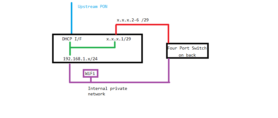
When you have a static IP allocation set up by AT&T, they assign you a /29 subnet of 6 IP addresses (Yes, the /29 provides 8 IPs, but you lose one for the subnet and the broadcast address for the subnet). They assign the sixth IP to the gateway itself so you’re left with five usable IP addresses. Since the BGW only has a basic five port switch, there’s no real way to say “this port is for public, that port is for private”. In this instance, if your host pulls a DHCP address, it’s effectively “behind” the BGW and on a private 192.168.1.x subnet. If you statically assign one of your routed subnet IPs to a host, it’s part of the public subnet.
Here’s a very basic diagram of the BGW with static external (red line) and DHCP internal (purple line) networking to help illustrate the issue. In this case, there’s a “router” with three interfaces, a DHCP public interface, a static IP address for the public subnet, and another static IP address for the private subnet (green lines).

Since I’m looking at bypassing the BGW, I will need another router and here’s where the ASR comes into play.
Replacing the BGW with … another router?
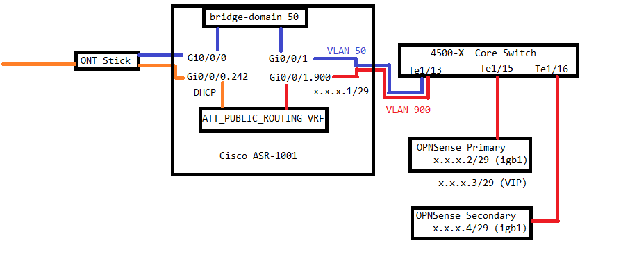
The fact that I have two firewalls in an HA pair means that I have to have the public subnet broken out into its own VLAN so I can attach both firewalls’ WAN interfaces to it as I can’t “split” one fiber into two for the firewalls. To do this, I’ll be using the Cisco ASR as the edge router for my network for AT&T. Additionally, a second VLAN will be used for out-of-band management of the GPON stick but I need to keep those two routes separate from the public Internet routing. Using a VRF will allow me to separate the out of band networking from the public subnet which I can then use to create the public VLAN.
In order for the VRF to know how to route the public IP subnet, the upstream interface has to pull DHCP from AT&T’s network. That IP address and the gateway information received as part of the DHCP handshake will set the upstream route for the public subnet. Aside from the routes, we really don’t care about the DHCP address, it’s just the connection to the upstream network.
In addition to the VRF, we will use a bridge-domain to effectively join the ONT stick and the downstream switch interface to VLAN50 so that it can be monitored. The VRF and the bridge-domain will be explained later. In the below simple diagram, I’ve outlined the GPON upstream network (orange), the public VLAN (red), and the management VLAN (blue). The LAN side VLANs off the firewalls have been omitted for clarity, otherwise the image would be much larger.

About the ONT stick…
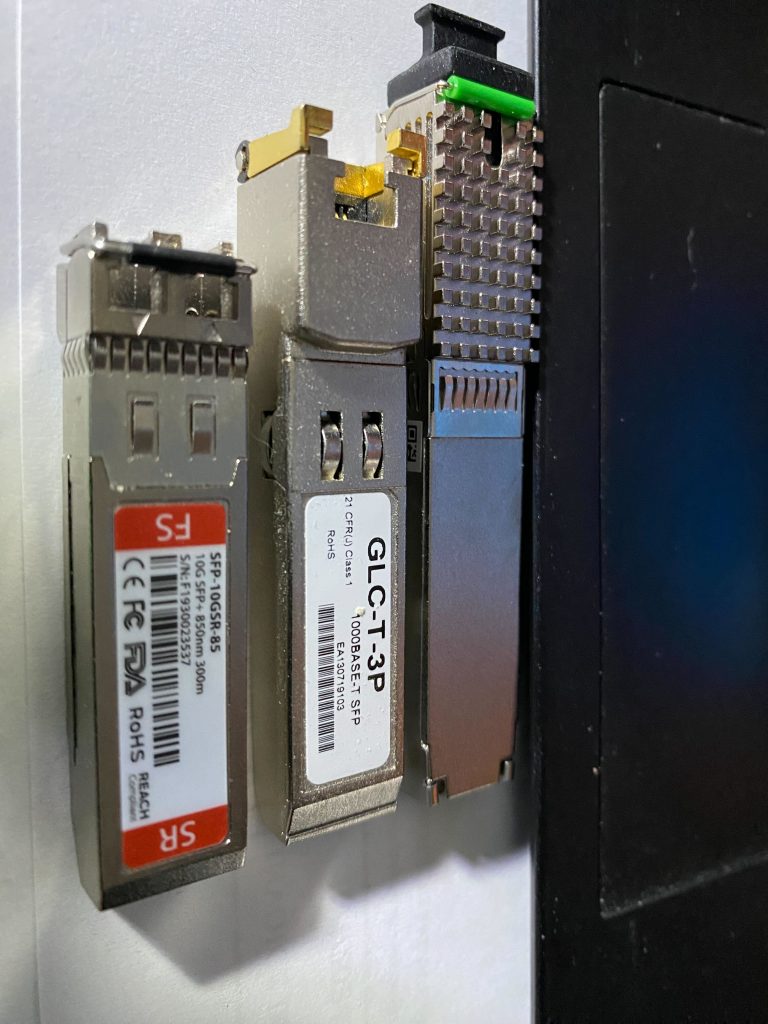
The GPON bypass method requires a specialized ONT-on-a-stick, a SFP+ transceiver module that houses a tiny embedded Linux computer that serves to terminate the PON fiber and translate it into Ethernet. People in the 8311 Discord recommended the use of an ODI DFP-24x-2C2 GPON ONT stick and loading their customized firmware to make management and access easier. The DFP-23X-2C3 is the SC/APC variant of the 2C2.
One of the reasons for the specific stick recommendations (for any of the recommended sticks for bypass) is the requirement that the stick is able to send a “Fake OK” message to the OLT (the ATT side of the fiber). This is because the OLT has the capability to send firmware updates to the BGW, but since we’re bypassing it, a “Fake OK” allows us to receive the command to update, but actually do nothing. In this way, we trick the OLT to thinking it’s upgraded our BGW, even though there’s no BGW in play.
As far as networking is concerned, the ONT stick has an untagged management interface that defaults to 192.168.1.1. A specific VLAN is passed through the ONT stick that is tagged on the router side of the stick. In order to get Internet connectivity, part of the bypass will be to discover that VLAN ID and configure the router accordingly. More on that later…

First step: Qualifiying your connection
The first step for performing the AT&T bypass is to qualify the connection. For me, that meant looking at the BGW320 and taking a look at how it was configured and looking at the physical connections so I could buy the correct transceiver. As mentioned before, there’s a wide variety of possibilities that must be filtered out before I make any purchases to avoid getting the wrong device.
In my specific environment:
- I have a public routed /29 subnet assigned by AT&T
- My fiber service uses a SC/APC connector (subscriber connector/angled physical contact – that is, there’s a slight angle to the polish of the fiber. My transceiver must also be SC/APC to avoid damage).
- My fiber connection is GPON with a 1310nm wavelength (seen from the transceiver in the BGW).
- Downstream of the BGW, I have two firewalls in an HA cluster. This requires that I have the public subnet broken out to a VLAN.
Step 2: Procurement! (Waiting is the hardest part…)
In my research, I was able to find the needed supplies from AliExpress, but seeing as how they are coming from China, the parts didn’t arrive here with any form of urgency like I’m normally used to seeing from eBay and other vendors. Turnaround time from order to arrival was about two weeks, but the items arrived without incident other than the long wait.
Here’s what I used:
- ONTi 2.5G SFP+ Media Converter
- This was used to provision the stick and confirm operation. When I started having switch issues, this helped eliminate the stick as the problem.
- ODI SC/APC GPON 2.5G ONT stick
- Note: Link points to an SC/APC converter, select XPON/APC from the “Color” selector
Third Step: Bypassing!
The directions for the GPON bypass of the AT&T BGW320 were really straight forward and I had the GPON stick setup in a few moments. Essentially, it’s flash the community firmware (twice), then run a bunch of commands that set configuration options, plug in the fiber, and run a few commands for discovering the specific configuration needed for the router. Finally, run a couple of commands to determine whether or not certificates are required as some AT&T installations require 802.1x certificates in order to negotiate a connection with the upstream network.
In my specific instance, I got really really lucky. I discovered my VLAN for the upstream network was 242, and I did not need certs for 802.1x. This makes the installation much easier, especially as I was not looking forward to learning how to do 802.1x on a Cisco ASR. Essentially, all I have to do is set the upstream VLAN (242), and clone the BGW’s MAC address to the upstream interface, and pull DHCP from AT&T. I get an IP address and effectively I’m on the Internet.
For some yet unknown reason, the ASR was only able to obtain an IP address on the VLAN DHCP interface when the transceiver was installed in the media converter. A gigabit copper SFP was used to connect the media converter to the ASR.
Fourth Step: Configuring the ASR.
For the ASR, we have a few considerations in play:
- The untagged management interface of the GPON stick should be on VLAN 50.
- The upstream Internet connection is on VLAN242 and we need to clone the BGW’s MAC to the DHCP interface.
- The public subnet will be VLAN900 and will be tagged through the ASR. This is done on the switchport that the ASR is connected to (TenGigEthernet1/13).
- We need a VRF to join VLAN900 and VLAN242 to route traffic.
- The downstream switchport will be configured as trunk with VLAN50 as native and VLAN900 as tagged. Vlan242 is not used past the ASR.
- We need an ACL to prevent public access to the ASR’s VTY lines (SSH connections).
For the purposes of configuration, we will be using Gi0/0/0 as the ONT stick port and Gi0/0/1 as the downstream switch port. The two other interfaces Gi0/0/2 and Gi0/0/3 will not be used.
In the sections below, I’ll be going over the specific commands for each section and explaining a bit about what they do in relation to configuring the ASR. At the end, I’ll post a cumulative “show running-config” to show all the interfaces as configured.
ASR: Defining the VRF
Defining the VRF is a very simple two-line command. Basically you give the VRF a name and define what networks you want routed with the VRF (IPv4, IPv6). For this setup, I’m just routing IPv4.
vrf definition ATT_PUBLIC_ROUTING
 address-family ipv4
!
ASR: Configuring the upstream VLAN interface
To configure the upstream VLAN interface, we need to set the MAC address of the parent physical interface, tell the VLAN interface to use the parent interface’s MAC address for DHCP, and add it to the VRF. This is specific to the VLAN discovery part of the GPON bypass. In my environment, the upstream interface is VLAN242 so we will need to create that subinterface. In the code text below, the mac-address line should be populated with the MAC address on the bottom of the BGW320.
interface GigabitEthernet0/0/0
 mac-address xxxx.aaaa.bbbb
 no ip address
 negotiation auto
!
interface GigabitEthernet0/0/0.242
 encapsulation dot1Q 242
 vrf forwarding ATT_PUBLIC_ROUTING
 ip address dhcp client-id GigabitEthernet0/0/0
!
ASR: Configuring our public IP subnet
In the “Static IP Networking” and “Other Router” sections above, we discussed how the AT&T gateway “steals” an IP address from the /29 that’s assigned. It’s not effectively stealing it as the subnet needs a gateway (router) to be able to route out. A public subnet with no gateway is just a block of IPs that can’t communicate, it’s not really useful.
For this configuration, we’re going to create VLAN900 on Gi0/0/1, our downstream switch link. This is done so that the downstream switch can deliver VLAN900 to where it needs to go for the firewalls and other devices that require public external IP addresses. The VRF will route traffic between VLAN242 and VLAN900. The “ip address” line should be set for the IP to be used as the default gateway for the routed subnet.
interface GigabitEthernet0/0/1.900
 description ATT_PUBLIC_VLAN
 encapsulation dot1Q 900
 vrf forwarding ATT_PUBLIC_ROUTING
 ip address X.X.X.1 255.255.255.248
!
ASR: Configuring management VLAN for the ONT stick
One thing to keep in mind with working with the ASR is that you’re not dealing with a consumer “router” that has an internal switch for convenience. Anything plugged into one of the four LAN ports on the back of a consumer router can talk to anything that’s plugged into one of the other LAN ports as they’re all on the same network segment. The ASR doesn’t have an integrated switch, the four ports on the device are all separate interfaces.
In order to bridge Gi0/0/1 untagged (VLAN 50 Management VLAN) to Gi0/0/0 untagged (VLAN 50 for the ONT stick), we need a “service instance”. In the service instance, we can set the encapsulation for the bridge and a bridge domain ID that tells the ASR that the two ports are allowed to talk to each other. In some configurations, a service instance can be used to tag and untag traffic between interfaces however we just need to bridge the two untagged interfaces together. The point is that other devices on VLAN50 on the downstream switch can communicate with the ONT stick even though they’re on separate ports on the ASR. Below is the configuration for the two ports and the BDI (bridge-domain interface) that binds them together. While you can use a different bridge-domain and service instance ID, you must be consistent. For example, if you use bridge-domain 100 on both interfaces, your BDI interface will be BDI100.
interface Gi0/0/0
 description GPON_INTERFACE
 service instance 50 ethernet
  encapsulation untagged
  bridge-domain 50
 !
!
interface Gi0/0/1
 service instance 50 ethernet
  encapsulation untagged
  bridge-domain 50
 !
!
interface BDI50
!
ASR: Configure ACL
Finally, with all that set up, an ACL must be defined in order to restrict access to the “line vty”s used to access the ASR remotely. Any IP address assigned to the ASR (either DHCP or static) potentially has access to the ASR. Using an ACL is mandatory for keeping it secure!
First we define the ACL, then we’ll change the line vty configuration to use the ACL going forward. In the sample code below, only 10.0.0.0/24 hosts can connect to the ASR due to Mgmt-ACL being applied to the line vtys. The “access-class Mgmt-ACL in vrf-also” also applies the ACL to inbound IP connections within the VRF. Make sure to set your ACL to permit only your local LAN to access the ASR.
The “no ip http server” and “no ip http secure-server” turn off the web-based UI for the ASR (it’s not very good anyways) and the “snmp-server community” line enables SNMP monitoring for the ASR but only allows inbound connections as defined in the Mgmt-ACL.
ip access-list standard Mgmt-ACL
 permit 10.0.0.0 0.0.0.255
 deny any
!
no ip http server
no ip http secure-server
snmp-server community YourSNMPCommunityHere RO Mgmt-ACL
line vty 0 4
 access-class Mgmt-ACL in vrf-also
!
ASR: Final configs
When all is said and done, the configuration looks something like this:
vrf definition ATT_PUBLIC_ROUTING
 !
 address-family ipv4
 exit-address-family
!
interface GigabitEthernet0/0/0
 mac-address aaaa.bbbb.cccc
 no ip address
 negotiation auto
 service instance 50 ethernet
  encapsulation untagged
  bridge-domain 50
 !
!
interface GigabitEthernet0/0/0.242
 encapsulation dot1Q 242
 vrf forwarding ATT_PUBLIC_ROUTING
 ip address dhcp client-id GigabitEthernet0/0/0
!
interface GigabitEthernet0/0/1
 description INTERNAL_VLANS
 no ip address
 negotiation auto
 service instance 50 ethernet
  encapsulation untagged
  bridge-domain 50
 !
!
interface GigabitEthernet0/0/1.900
 description ATT_PUBLIC_VLAN
 encapsulation dot1Q 900
 vrf forwarding ATT_PUBLIC_ROUTING
 ip address x.x.x.1 255.255.255.248
!
interface BDI50
 no ip address
!
ip access-list standard Mgmt-ACL
 permit 10.0.0.0 0.0.0.255
 permit 10.1.0.0 0.0.0.255
 permit 10.0.5.0 0.0.0.255
 deny   any
!
!
snmp-server community YourSNMPCommunityHere RO Mgmt-ACL
!
line vty 0 4
 access-class Mgmt-ACL in vrf-also
Final connections and a photo of the ASR in action!
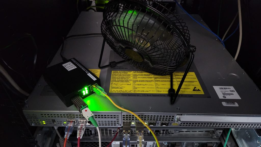
With Gi0/0/0 connected to the media converter, Gi0/0/1 connected to the upstream switch, and management and console connections connected, here’s what the ASR looks like. The fan is there to provide cooling for the SFP stick sticking out of the media converter.

Troubleshooting and other gotchas!
The hardest part of the AT&T bypass for me was getting the DHCP interface to pull an IP. I’m still not sure if it is relating to a DHCP timeout, misconfiguration, or SFP incompatibility, but the result was the same, essentially a failure to pull a DHCP address. There were several periods where I just gave up and dug the BGW out of the catacombs that is the parts closet. The good news is that if you can get to a point where you’ve pulled a DHCP address, you’re effectively on the Internet and your public subnet will route.
In my experiences with the bypass, I found a handful of commands to help diagnose and debug the DHCP interface:
- (no) dhcp debug detail – This produces significant output that shows what the DHCP daemon is doing in relation to pulling an IP address. I recommend running this in another session so it doesn’t interfere with your primary session. Disable output by typing in “no dhcp debug detail”
- release dhcp Gi0/0/0.242 – This instructs the DHCP daemon to release a pulled DHCP IP address and stop trying to pull a DHCP address.
- renew dhcp Gi0/0/0.242 – This instructs the DHCP daemon to start trying to pull a DHCP IP address.
- show dhcp lease – Shows a list of currently pulled DHCP leases. Will return blank if no DHCP interface has an IP. The ASR will show them as “Temp” since DHCP can change, but the IP will persist as long as AT&T has their DHCP server configured.
- show interface summary – Prints a table that shows all their interfaces and states (up/down).
- show run interface Gi0/0/0 – Shows the running configuration for interface Gi0/0/0. You can specify any interface present in the ASR. For VLAN interfaces, specify the subinterface (e.g. Gi0/0/0.242)
- show interface Gi0/0/0 – This shows the interface status information, IP address, and link state as well as interface counters for the interface. This works on any interfaces on the ASR.
- show vrf – This will show all the defined VRFs on the ASR including the protocols they support and what interfaces are connected to them.
I’ve also discovered that for unknown reasons, the GPON stick will stop responding to its management IP address if there’s no traffic on its management interface. As a quick hacky solution, I’ve got ‘ping’ running in a screen session with the whole intent to keep that interface active.
Just because it links up, doesn’t mean it’s good!
Early on in the bypass misadventure, I tried originally to get the Cisco 4500X to perform the public subnet routing, however from the outset I was faced with problems. The 4500X’s interfaces will link at either 1G or 10G while the GPON stick would link at 1G, 2G, and 2.5G. Between the stick and the 4500-X you’d think that they would negotiate and link at 1G, but that wasn’t the case. Even with a green triangle on the physical port and the interface showing a 1G link in “show interface status” on the switch, the SFP stick would not answer pings and the VLAN subinterface would not pull a DHCP address. To make matters worse, I tried using a genuine Cisco 1G copper SFP to the media converter and the conditions did not improve.
One of the quirks to the GPON stick is that it will obey sending RX_LOS to the connected device which disables the SFP interface. Despite the fact that the SFP side of the ONT stick is a separate logical interface than the PON side of the stick, I found that many times I couldn’t talk to the stick if the PON side of the stick wasn’t attached to the incoming fiber.
On top of that, I found the AT&T DHCP server to be very unreliable. In some attempts, the DHCP interface would near instantly get an IP. In other attempts, the DHCP interface would link after 20 minutes, and in some other attempts, it took well over an hour before the DHCP interface would pull an IP. In all instances, now that the ASR is running and everything is routing as expected, I’m not wanting to touch the ASR until I have to due to the delicate nature of being able to pull a DHCP address.
Final Thoughts
On a scale of 1-to-10, this was definitely one of the harder projects I’ve done, I think I’d give it a 7. There were factors working against me, namely not having any prior experience with configuring the ASR nor familiarity with how GPON networks work. Having an HA pair of firewalls also didn’t help because there were additional requirements that made this a lot less plug-n-play than a single firewall configuration.
A lot of people on the 8311 Discord have single firewalls so for them it’s as easy as inserting the stick and configuring their router to use the stick and the VLAN subinterface. Because I can’t split the single fiber into two firewalls, that was not an option for me.
All in all, I feel good about performing the bypass. I know for a fact that the ASR can route gigabit traffic (the routing bandwidth of the ASR is 2.4Gbit) and my firewalls are able to keep up with multi-gigabit routing. Even though I only have a 1Gbit Internet connection, I know for sure that the ASR and my firewalls are up to the task. I also know that I can use SNMP monitoring to see actual interface utilization and can set up alerts to monitor the ONT stick in case we do have an Internet outage. It’s definitely overkill, but then again, so is the rest of my network.
Happy Hacking!
FIRESTORM_v1