Add a real lasersight to the Nerf Nitefinder
by firestorm_v1 on Nov.24, 2009, under Hardware, Toys and Games
Well here’s the seccond post as promised. These posts should also proves that you don’t have to know sick computer skills or mad hardware to be able to pull off some bad ass hacks. In this post, we will address the Nerf Nitefinder and it’s so-called light sight. While the verbage does get around the expected/anticipated lack of a good lasersight, this post will walk you through adding a real laser sight to your Nitefinder. Read on for more details along with lots of pictures.
Foreword:
During Xmas/Yule/whatever, I was given the lovely gift of a Nerf Nitefinder handgun with a touted light sight. Upon final inspection however I was dismayed as was the person that bought it that the device did not contain a real laser sight as evidenced by all the commercials on TV. Not to be let down by a mere exaggeration on Nerf’s part, I set out to create a lasersight for this not so lasersighted weapon of nerf destruction.
While I was researching this topic, I came across many many websites about Nerf modding, but everyone’s solution seemed to be more of writing off the nerf sight and duct taping a keychain laser pen to it. If I was going to do something, I was going to do it right damnit, and Duct tape wasn’t going to be the solution. After a few Nerf wars, I also had become weary of having to recalibrate the optics because a frenzied firefight resulted in a slight bump to one of the pieces of plastic that jutted from the sides of the optics package at the end of the gun.
So here it is, the fruits of my hard labor, and my beer, the instructions necessary to install a lasersight in the Nerf Nitefinder.
Required Tools and Parts:
- Nerf Nitefinder
- Some common 2 battery laser pen
- Note: The 2 battery part is CRUCIAL, a 3 battery pointer won’t work as well.
- A sacrifical NERF dart.
- A soldering iron with solder
- Small tip Philips screwdriver (+)
- Knife
Total Cost: ~$20.00, depending on cost of laser pointer.
Note: The reason why a 2 battery laser is important is because the Nitefinder itself only has two batteries, equalling about 3.0vDC. Most laser pens take 3 or more batteries which is 4.5vDC or more (each cell is typically 1.5v). Since I didn’t feel like carving out a battery holder, the 2 battery laser just made sense.
Pre-Analysis:
For those of you considering, this is what the light sight looked like before the hack was completed.
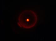
This image was taken with all the lights in the room off, the gun about 2 feet away from the wall and the camera set to nite mode. The camera didn’t capture the “halo effect” that made the dot rather distracting. The dot wasn’t really a dot either, it was more of a funky “U” shape, which is explained later. There’s definately room for improvement here.
Phase 1: Prep the gun.
Start off by removing all the screws, the battery cover and the batteries from the gun. It will look something like this:
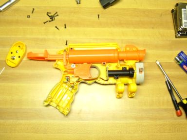 Of particular note is the circuit board attached to the red and black leads. This is the source of the “light”. The picture below shows us that it is nothing special, just a high intensity red LED and a resistor.
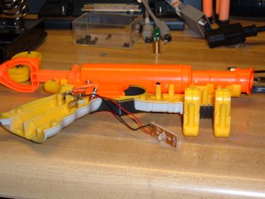
Go ahead and unscrew the two black screws holding the black tube down. This is where we will be doing most of our work.
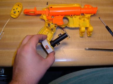
The entire sight module comes out. It consists of the aforementioned light board, the black tube and the housing that protects the optics package. Remove the light board from the end of the black tube.
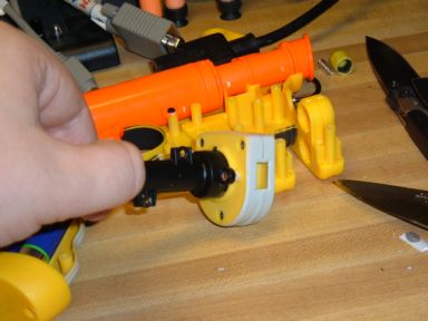
This picture shows one of the two screws necessary for attaching the optics package to the sight. Remove both screws and carefully use your knife to scrape away the glue holding the two parts together. Set aside the tube, optics package and the gun for now.
Phase 2: Rip the pointer apart.
A special note: Not all laser pointers are created equal. Some modules like this one were press-formed together, while others might have a retaining nut or some other screw-in device. It is especially important to pay attention to detail as there is a piece on most laser diodes that you do not want to unscrew and that’s the focusing element of the laser itself. This particular pointer was press-formed together, which made it an easy harvest. I would avoid using the lasers that multiple tips, as this is an almost sure fire screw-on situation that might just leave you screwed in a bad way.
Start by removing the batteries, Take special note of which end is positive, typically it’s the end that you unscrew to get to the batteries. Polarity matters later on.
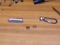
With the knife, locate the seam between the head of the laser pointer and the body. and press hard to start seperating the two pieces.
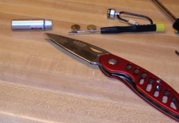
After you get it scored enough, or if you feel the head loosening, gently pry up using the knife blade or a screwdriver. You will end up with something like this.
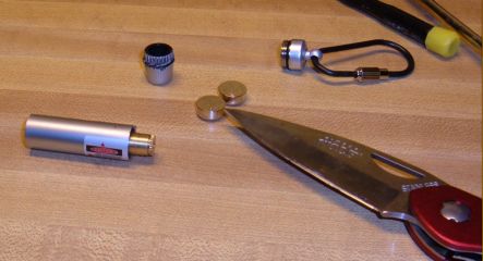
The brass cylinder is the actual laser diode we came for. This particular model is press-formed together and is held together by a star shaped collar. This collar was easily moved by a very fine screwdriver.
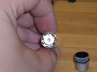
Before you attempt to extract the laser, look inside the tube and see what you might need to do about getting that switch out of the way. This laser had a rubberized switch so I didn’t have an issue but you might. If necessary you can destroy the switch as we will not use it, but MAKE SURE IT’S THE SWITCH AND NOT A CAPACITOR. In the picture below, the switch is the little white boxin the lower right hand quadrant. The other white pieces are parts of a plastic sabot made to hold the board in place.
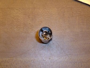
After successful extraction, you will have something like this.
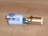
Now that we have the circuit out, it’s time to find out where we’re going to solder. Remember earlier when I said pay attention to the batteries? This is why: In most device, the chassis is ground and the switched power is hot or positive. If the batteries plus sides were all pointed to the spring, then the pointer has a cold chassis, meaning that it is always connected to negative. If the batteries plus sides were all facing the unscrew cap for the battery compartment, then it has a hot chassis. This is one of those your mileage may vary things. Mine had a hot chassis, which means that the switch was controlling the negative or ground side of the batteries. An examination of my circuit board showed me the pads for the ground quite easily. Remember, that the white box is a switch and we will remove it soon.

This is the critical part. Since my laser pointer is hot chassis, that means that the circuit is getting its power from another contact. The only contact that is evident is the brass casing of the laser diode itself! Since this laser diode has three contacts, it is extremely important to locate the contact that does not have a ring around it and that you can see solid metal all around. This is the casing lead and where we will be attaching our positive lead. Alternatively, if you see a lead labled Vdd like this circuit board does, that is the location of the positive connection. Vdd=power, GND=negative or ground.
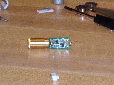
Now it’s time to fire up that soldering iron. Detach the red and black leads from the light board on the gun, set aside the circuit board. On the laser pointer, remove the switch and the spring end.
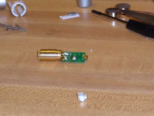
Looking at the solder traces (the bright green lines) you can tell where the switch was. You will want to attach the black lead to the pad that does not go to the spring. This bypasses the switch and leaves it always on. (Remember: the trigger switch will control the power to the laser.)

If you still have the shroud and the star shaped retainer, remove them now. They are not needed and can be discarded. After soldering, it is a good idea to check that the diode still works and that we haven’t shorted something. Carefully connect the two AA batteries and press the trigger button. The Laser should light.

Now that’s all said and done, we have a functioning laser diode, now it’s time to mount it in the tube. Grab your sacrifical nerf dart and set it alongside the black tube with the laser diode circut. You will want at least a 1/2 inch.
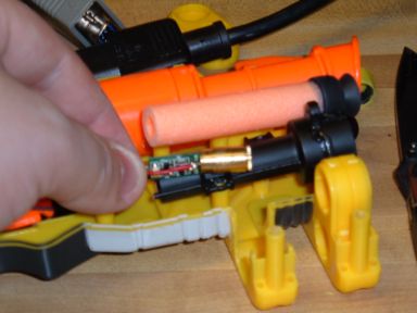
Cut the dart enough so that there is no foam over the end of the brass laser diode and so that there is enough foam to cover the circuit board.
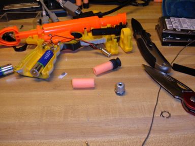
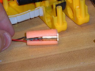
Next, slit the cut piece lengthwise and place the laser assembly inside.
Grab the optics package and set it on the table, screws side up.
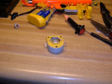
Remove all three screws, and open up the optics package.
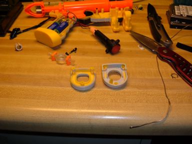
Remove the lens, and the two orange clips. Discard these, we don’t need them and they distort the laser light. Reassemble the optics package and go to the next section.
Phase 3: Reassembling the sight
This is going to be almost as challenging as getting the laser diode out. You will need to take the foam wrapped laser assembly and squeeze, shove and stick it in the small end of the tube. Make especially sure that there the foam stays covering the brass diode and that you don’t destroy the circuit board. The end result will be something like this.
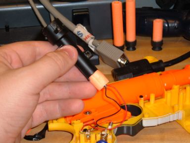
Looking down the tube, we will see the laser diode still there with nothing protruding over the little hole in the brass. This is actually the laser’s aperture and any blockage will cause the dot that the laser projects to look weird.
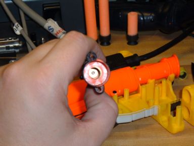
Reattach the optics package to the barrel and screw the barrel to the gun. You may need to trim the foam in order to get the gun halves to get back together.
Phase 4: Now, about the firing distance
The following image is an exploded view of the assembly at the top of the gun. This is held in place by two screws and is easily removed. The parts in order from left to right are:pressure chamber, spring, regulator, stabilizer tip, barrel. For max effectiveness, remove the spring and the regulator. (items 2,3)
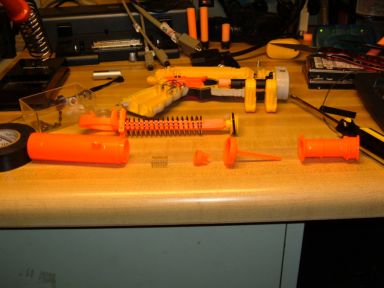
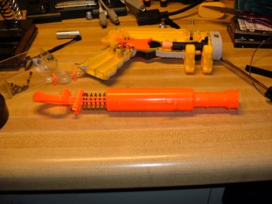
Reassemble the barrel like shown and reattach to the gun. Make sure that all springs are in their proper place, less the regulator spring.
Phase 5: Calibration
Now that both mods are in their final stages of being complete, you need to calibrate the gun. Put the other half of the gun on, but do not use any screws just yet. This will be a process of fire and adjust over and over again until you are satisfied. There are no pictures for this phase, just remember that if your gun shoots to the right of the laser dot,wiggle the laser to the left. If it shoots low, wiggle it down. After a few shots, you’ll have it zeroed in and working fairly well.
The reason why I didn’t calibrate right after we put the sight back on was because of the firing distance mod. If you had calibrated and then performed the mod, the calibration would be no good because of the considerable difference between the air pressure hitting the bullet pre and post calibration.
Phase 6: Give the cats a new reason to hate you.
If all is well, the gun is sighted in and working, go ahead and close it up! You’re done.
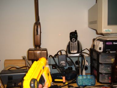
See, now that’s a real lasersight! Happy Nerfing!!
FIRESTORM_v1

July 4th, 2010 on 8:50 pm
Did you leave the one resistor in? The one near the battery compartment that attached to the switch
July 6th, 2010 on 11:19 am
Hello Inept77:
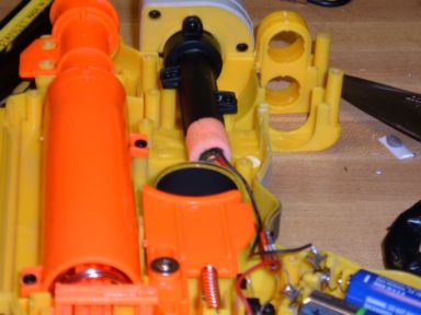
My nitefinder had the resistor on the LED board. The white cylinder on the battery compartment is a fuse. I would recommend leaving that in place.