Basic Stamp: A quick guide on using a legacy joystick
by firestorm_v1 on Feb.03, 2010, under Embedded devices, Hardware, How-To's, Microcontrollers

In this post, we’ll be going over the basics of using an old regular PC-gameport joystick with Parallax’s Basic Stamp powered Boe-Bot. This howto will have all the information you need to get started including code, schematics and a parts list. We will be covering how the joystick is wired and how to go about interfacing it with the Boe-Bot for an easy to use and easy to expand analog control method for your Boe-Bot. Next step, world domination!
Foreword
The joystick is something that has been around quite a long time, even longer than computers. The idea of being to control something on-screen by using a joystick is one that takes almost no learning curve, is easy to start and you only end up getting better. Even today in modern gaming, it is easy to find controllers with at least one analog joystick on it. My Xbox 360 controllers feature two sticks per controller which give the gamer a very precise method for movement and aiming accuracy, something that buttons can’t quite provide. As long as I’ve been working on computers, I always remember using PC analog joysticks in my games.
Nowadays, the modern PC joystick has all but gone the way of the dodo, however those few that are around now are USB and have a ton of buttons. The legacy joystick (or “gameport” joystick) still has a bit of usefulness in it and today we will be covering how to get it to work with a Basic Stamp microcontroller.
Of course someone’s going to ask, “Why use a PC joystick?, Why not (insert control method here)?”. My answers are:
1: Cost – The PC joystick used in this tutorial was bought at a Goodwill for $3.
2: Ease of use – Once you have programmed your application, you just grab it and go. There’s no need to go over complex control methods or trying to remember what does what now.
3: Low Parts Count – In this tutorial, I used two capacitors and six resistors to get the joystick working. Most other control schemes require a lot more parts.
Basic Theory of Operations
The way an analog PC joystick works is not very complex at all. You have a stick which is capable of moving any position along two axes (X and Y) and with two switches or “buttons” for interaction. The position of the stick is detected via two variable resistors usually around 10Kohm, one running horizontal (left/right) and one running vertical (towards you/away from you). The computer would send a pulse out to the joystick and get return values from the variable resistors. Using the returned pulse it could then decide on what action to take, how far/fast to move your character, etc..
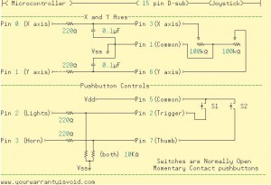
The two buttons (or more) are detected through simple momentary contact switches. If the switch pin was high, then the button was depressed otherwise, the button was released. These button switches are normally open and while the gameport pinout supports up to four buttons, additional buttons were made by figuring out how to multiplex them as shown in the chart below: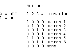
When using the PC gameport joystick, you would need to go through calibration which taught the computer the limits of your axes and the button layout. Because variable resistors are not terribly accurate across manufacturers this calibration was a requirement as no two joysticks, not even those made by the same manufacturer, would behave exactly alike. There would always be minute differences between the joystick’s behaviors so the calibration was a way to standardize the measurements and clean up the inaccuracy of the joystick.
In our tutorial, we will be using a two-button model. This joystick is a very standard stick and has a trigger button and a thumb switch button. It connects to the computer via a 15 pin D-sub connector usually to the sound card which has a Gameport connector on it. This connector is usually orange on newer motherboards, if it exists at all.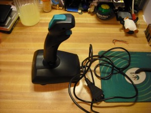
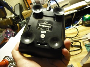
On the bottom of this joystick, there are two sliders. These two sliders can be used to “tune” the position of the VRs in order to be able to get the best range of motion for the stick. You may need to use these during the next step for calibration. Here is a picture of the bottom of my joystick. The large circular things are suction cups which help keep the base down on the table while you move the joystick around:
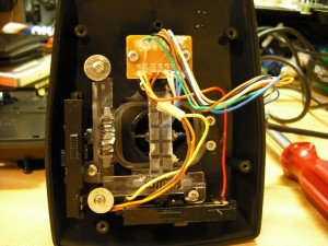
After taking the bottom off, we can see the setup of the two variable resistors (VRs). Unlike most joysticks this one uses linear VRs and not the rotary VRs (sometimes called pots) that are commonly found for volume controls. We have oneVR on the left for the Y axis, and the other one along the bottom for the X axis, some support hardware and a small PCB:
The little circuit board at the top of the stick doesn’t conceal any electronics, It’s only a bypass as shown in these next two images: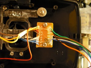
This picture is of the bottom of the circuit board, As stated before, this only acts as a pass through to make wiring the joystick easier during production.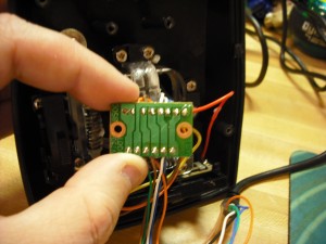
Here is a picture of one of the two linear variable resistors. These are 100Kohm but yours might be different: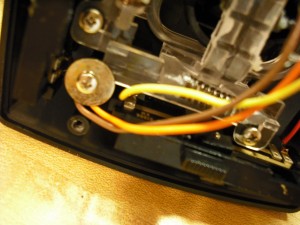
Now that the joystick has been opened up and we know all it’s secrets, it’s time to start on the interface for the BOE-BOT.
The interface circuit
The interface for your joystick is actually quite simple. You will need the following items:
- A 15 pin female D-sub connector with ribbon cable – I used the one from an old PC that I had many years ago. The long ribbon was perfect for this job.
- 4x 220ohm resistors
- 2x 10K resistors
- 2x .1uF capacitors – Note: I used ceramic capacitors in my project as they are easier to work with however in theory electrolytic capacitors should work as well. If you use electrolytics, please pay careful attention to the polarity as electrolytics can explode if hooked in backwards and may risk hurting you and/or damaging your microcontroller.
- Jumper wire as needed
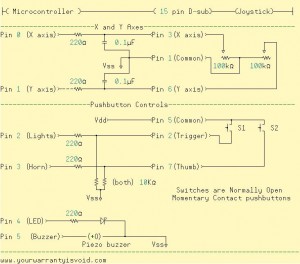
This will provide the basic parts needed to perform our calibration test. You will need to hook up the parts as shown in this schematic below. Click on the image for a full size one if you need it.
Here is a full pinout of the PC gameport connector that shows all of the various things that the pins are used for: (Pinouts obtained from pinouts.ru – a good site to have handy)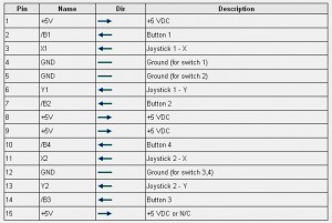
In my D-Sub connector, pin 4 and pin 5 are shorted together however this may be done either at the joystick end or in your D-sub cable as well. When in doubt, test it with a multimeter. If you find that during your calibration test, your buttons do not respond at all try examing those two pins to make sure that they are both shorted together. WARNING! Although the pinouts.ru pinout provided above has some things labeled “Ground” and “+5VDC” use my schematic as the final verdict. The reason for this is the pinouts.ru site describes the joystick’s gameport connector on a computer. Since we are not using a computer and this is not a digital joystick, I have changed some of the meanings of the pins as shown in my schematic. If you hook it up differently, you might damage your microcontroller.
Calibration Software
Now that the interface is built, we need to write the code needed for making the BOE-BOT “read” the joystick and to make it do stuff. We will be using the RCTIME function of the Basic Stamp to charge and time the two .1uF capacitors. By timing their discharge rates, we can then mathematically calculate the position of the joystick.
As far as the buttons go, they are just as easy as any other two buttons for your microcontroller. The BOE-BOT will monitor pin2 and 3 and if they are brought high (by pushing a button) the BS2 will sense it and perform whatever action you have programmed. For now, we are just getting the calibration information and to make sure everything works properly. The tags for “Lights” and “Horn” will come in the next section.
You can download the source code called “BS2_joystick_diagnostics.bs2” from my downloads page, or here is the direct link You might need to right click on the link and go to “Save As”.
After loading it into your BOE-BOT, be sure to leave a debug window open, as this is where you can see the RCTIME counts and the buttons. You may notice that the values will be all over the place and will constantly be changing but this is normal. Play around with it a bit and get a general feel for how your joystick works.
If for some reason, your RCTIME is stuck at 0, this indicates that the Basic Stamp is not seeing the capacitor or is not sensing the capacitor’s discharge. You will need to check your wiring to make sure everything’s lined up. If need be, you can use a 100Kohm resistor between pins 1 and 3 or between pins 1 and 6 on your 15 pin D-sub connector to test. If RCTIME shows up there, then use the multimeter on your joystick’s D-sub cable and make sure that you can see the resistance changing on those two sets of pins. If you get no connection on the joystick, you could have a bad joystick on your hands.
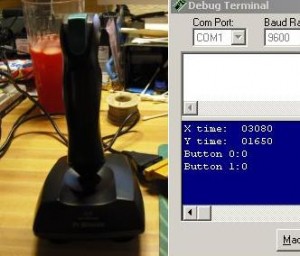
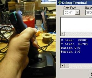
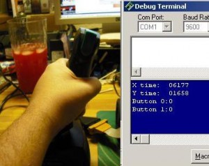
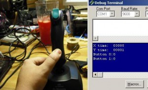
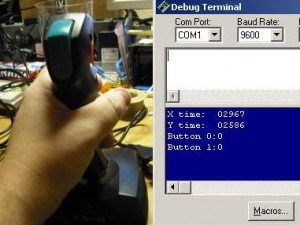
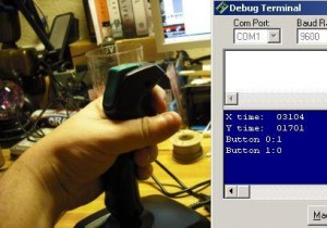
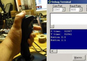
Here are the images of my RCTIME output along with a picture showing the position of my joystick. You will have different numbers, but the format is still the same.
Once you have a “feel” for how the joystick responds, let’s actually do something with this. You will need to figure out the zones on where to apply the speed settings. The BS2_Rover application contains routines that can filter out and adjust pulses sent to the servos however this requires a bit of calibration (hence the calibration application). All you need to do is to figure out where your joystick should switch between off and low, low and medium and lastly medium and high. The reason for this is that for precise movements, we don’t want the BOE-BOT to lurch out of control, and while high speed all the time might not be a bad idea, it can be cumbersome trying to get into a small space with it.
Getting it to work
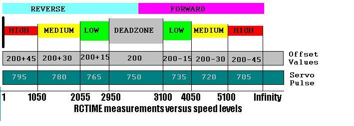
Go ahead and download the file “BS2_joystick_rover.bs2” from my Downloads page or via this direct link. Load it up in your Basic Stamp Editor as now we need to make some adjustments to it. I’m pretty sure that your joystick will behave differently than mine will which is why my code won’t work out of the box. Well let me rephrase that, the CODE will work, but the joystick calibration will be off. Using the calibration application above, you can get the RCTIME values needed to make the servo speeds and the directions work properly. Look at my speed chart below and you will get a better understanding how the BS2 rover works:
With this chart you can see at which points the BOE-BOT will change speeds. You will need to make a similar chart for your joystick using the calibration program and then you can edit the BS2 Rover file and add those settings in the two GOSUB statements. The DEADZONE is important as this is the point where your stick’s RCTIMEs will fall when no one is touching the joystick. It is important to have a deadzone that matches your joystick to prevent your BOE-BOT from running away from you.
Something of note is that my chart starts at “1” and not “0”. This is because if the VR is at minimum resistance RCTIME will still return a “1”. The only time RCTIME will return a 0 is if there is no load for the capacitor to discharge to, for instance when the joystick is disconnected. In the event that RCTIME does return a 0, then we will send out the same pulses as what we send out in our deadzone so that way our BOE-BOT does not move once the joystick is unplugged.
Here’s how the two subroutines work in a nutshell. You start off with a pulse value of 200 and depending on where your RCTIME is, you will either add to it which makes the servo rotates one direction at one of three speeds or you will subtract from it which will make the servo rotate the other direction at one of three speeds. Once the comparisons are done, you add a constant value of 550 to the pulse value. This pulse value will then get pulsed out to the servos and the wheel turns.
The reason 550 was selected was because 550+200 = 750 which is the point at which your servos do nothing. In the speed chart below, we can see how the offset affects the servo pulses and how each of the two items correspond with the speed levels:
 So now that you understand the two subroutines, go ahead and edit them to match your joystick’s behavior and desired positions.
Extra fun stuff
Now that we have the complex part out of the way, we can also instruct the BOE-BOT to do something when we press the buttons on the joystick. I have added a buzzer, a 220 ohm resistor and an LED to the last schematic so that now when we press the trigger button, the piezo buzzer will make a beep-beep sound and when you hit the thumb button, you will see the LED turn on and off. Here is the updated schematic with our new parts. (Click on it for a full size image)
Once you have made the needed changes to your code, there’s one last thing that needs to be done before you upload it to your BOE-BOT. Check one last time and make sure everything is set properly, otherwise you might have unexpected results. If all looks well, go ahead and upload then try it out.
Here is a video I made of my BOE-BOT in action. For this test, I used a white ultrabright LED which produced a lot more light than the standard LEDs that came with the BOE-BOT.
The “chugging” motion is normal. This is the BOE-BOT, checking the RCTIME of X, pulsing out the X servo, checking RCTIME of Y, pulsing out the Y servo, checking the buttons then repeating itself. Since the BOE-BOT is a single-process chip, it can only do one thing at a time otherwise the motion would be a lot smoother than it is. If you are using the Propeller, you will get smoother action out of it by dedicating a COG to monitoring the joystick’s X and Y axes, and another COG to controlling the servos.
Last words
Using an analog joystick for your robotics projects can be an excellent way to bring an easy and intuitive interface for robot control into your project and I hope that this article shows you how easy it is to use. It doesn’t take any fancy coding, expensive hardware or overkill designs, just some basic knowledge of how RCTIME works and a few bucks for the joystick. With a minimal part count, you can increase the flexibility of your robot’s design quite easily and you might even save yourself some programming headaches later on.
As always, thank you for reading.
FIRESTORM_v1
4 Comments for this entry
2 Trackbacks / Pingbacks for this entry
-
Interfacing with an analog joystick - Hack a Day
February 6th, 2010 on 2:12 pm[…] put together a tutorial about interfacing an analog joystick with a microcontroller. These analog sticks are easy to find; he got his from Goodwill but we’ve got a couple in our […]

February 8th, 2010 on 6:13 am
hahaha…. Chugging motion…
October 22nd, 2010 on 3:53 am
heres a question for you….I have an old USB joystick and I have some software that allows me to design projects that can sense if a fire button is pressed.
Since this is a just a simple momentary switch arrangement of 2 states ( on / off )….im just wondering here…what simple (sensors) could I use to trigger this state and have my software read it? – obviously I cant use things like an RPM meter or other thing that is a variable..but something that simply senses an on or off state that replaces my finger on the fire button. – Any ideas?
Thanks in advance guys.
October 25th, 2010 on 10:44 pm
That’s a good question. I’m not too sure I’m following, but are you attempting to keep the USB hardware intact? If so, I’m not sure that the BS2 sensing and the USB hardware would be compatible as most USB compatible microcontrollers use a 3.3v logic voltage instead of the Basic Stamp’s 5V logic voltage. Additionally, the BS2 can not do USB host support natively, it would definitely require cracking the case open and fiddling around with the wiring.
I believe that there are some AVR’s and PICs that support USB host mode directly so if you’re handy with some C programming, you may be able to write a basic USB host driver necessary to read the triggers that you’re looking for.
Good luck!
FIRESTORM_v1
May 20th, 2015 on 6:01 am
I don’t know you still reply or not. I have just started working on joysticks and there is a thing that keeps bothering me about analogue joysticks. There are two variable resistors for two axes X & Y. One potentiometer is enough for letting us know about the movement of joystick in x-axis. Is it ? so one center pin of the variable resistor is enough to work with . But when it gets to connected to PC through D-sub 15 it takes two pins for x-axis. i.e (X1 & X2 get connected with Pins 3 and 11 of D-sub 15 respectively).The same question arises for Y-axis. it could be a rookie question … help me out please.