Dead Dockstar Resurrected with JTAG!
by firestorm_v1 on Sep.08, 2010, under Embedded devices, Hardware, How-To's, Linux
The reason I haven’t written any more about my fun with the Dockstar was that due to an unfortunate set of circumstances I was left with a bricked dockstar. (read: I did something stupid.) After performing a lot of research and thanks to a bunch of people over at the PlugApps.com Forum site who helped me, I was able to get it running. Read more for a complete list of what you will need including how to build an adapter and where to get the needed JTAG kit.
Before we begin
This document demonstrates how to recover your Dockstar and upload a custom bootloader to it using a JTAG cable. JTAG is used for low-level in-circuit debugging of embedded applications and is very hardware specific. If you are familiar with working with Linksys routers and uploading custom firmware to them, you have heard of the term bricking and you have more than likely heard of something called JTAG that is used to recover it.
Because of the nature of JTAG and the fact that manufacturers don’t typically like us having access to the JTAG port, these ports are often hidden in many different locations, usually unmarked or unpopulated headers, or other odd locations and is the way that the manufacturer loads the firmware for the very first time on to a new device.
By using JTAG, we can place the hardware into a “debug” mode where we can manipulate the microprocessor’s core functionality. We can also send instructions to it, monitor responses from it, or even pause the chip, leaving it in a state of suspended animation until we issue the command to start it up again or reset the device.
In this particular howto, we will cover how to use the debug mode of the Marvell chip in the Dockstar to upload a new boot loader in order to rewrite the bootloader to the onboard Flash which will result in a working, new Dockstar. Please note that if you have NOT bricked your dockstar, there is no need to perform the steps in this howto. This is only for bricked dockstars that have been verified with a serial adapter to be dead. (A dead dockstar will produce NO serial output and the front panel LED will not light up when power is applied.)
Legal Disclaimer
By performing the steps outlined in this document, you agree not to hold firestorm_v1, YourWarrantyIsVoid.com or any other linked sites, forums, companies, liable if you really screw something up. You can also not hold any of these entities responsible for data loss, physical damage, emotional trauma, spousal abuse or any other act of whatever god(s) that you may have happen to you. In short, Read twice, type once, hit enter and don’t screw up. If you’re at this point, then you’ve already come to terms that your dockstar may be unrecoverable already so deal with it.
Parts List
In order to perform this recovery, you will need the following items:
- The dead seagate dockstar and power supply.
- A handful of 2.0mm female connectors or one 2.0mm female connector with at least 10 pins (5 pins in 2 rows)
- A 10 pin header that matches your PCB 2.5mm spacing (again, 5 pin, 2 row)
- A bit of holed PCB board 2.5mm pin spacing. (Radio Shack is good for this kind of stuff)
- A CA-42 cable with the appropriate pins as outlined in my previous Dockstar post.
- A handful of extra breadboard jumpers.
- Superglue
- A Windows PC (2k or XP, untested on vista/7 although plugapps forums says it should work.) with a Parallel Port
- Whatever provisions needed for the CA-42 cable to work properly. (I have to use a linux box to SSH to, you can do the same or if your Windows computer works with the CA42 cable, you can use that as well. You don’t need two PCs for this operation.)
- A TAIO Buffered/Unbuffered “Universal” Parallel Port JTAG module kit (Here’s the eBay seller where I got mine, ~$21.00 out the door) and a Parallel cable extension (Male to Female) so that you can reach it without having to get behind your PC. For my setup, I used an old iomega Parallel/SCSI Zip drive cable. I also recommend the ebay link as this is the seller that I purchased mine from and it comes with a lot of extra jumpers that are very useful for this project.
- A USB A to USB mini B cable (for powering up the JTAG adapter).
- Glue gun with extra gluesticks
- Heatshrink tubing and lighter/heat source
- In lieu of building/reinforcing your JTAG cable, you can use a laptop hard drive adapter (3.5 IDE to 2.5IDE) if you’re in a pinch and just need to get it running.
In addition to the above items, you will need the following software applications:
- Kragorn’s copy of dockstar.cfg – Mirrored Here
- A copy of OpenOCD – Mirrored Here
- A copy of the Jeff Doozan’s custom USB-boot capable u-boot (Recommended!) (Mirrored Here) or a copy of another factory or custom uBoot. If you want to compile your own, there’s a great write-up here: http://jeff.doozan.com/debian/uboot/
- A copy of PuTTY for Serial/Telnet communication. You can download it here.
Getting Started
This howto will be divided up into several sections:
Section I:Building an adapter cable – This section will cover how to build the required cable from spare 2MM connectors or if you already have the proper cable, this will describe how to reinforce it for repeated use using heatshrink tubing. I call it a smokestack cable because it resembles a small smokestack sticking out of the Dockstar’s mainboard.
Section II: Wiring it all up – This will cover the Dockstar’s pinout, the TAIO parallel port pinout, the serial port pinout and how to wire it up together.
Section III: Performing the JTAG recovery – This is where the actual recovery process takes place now that we have everything wired up.
Section IV: Notes and credits – As much as I’d like to say this was all my doing, truth is it’s not. I couldn’t have done it without some great people from the PlugApps forums.
Each section will have lots of pictures that you can use as a guide to make sure you’re making the right connections.
BIG FAT OBNOXIOUS WARNING!!!
Although there are as many JTAG adapters on the market as there fish in the sea, I can not cover each and every device’s unique configuration options. Generally the JTAG port is a universal standard but many vendors implement their own standard, have other standards that they choose to leave out and their pin configurations may not match what is given here. This article is based on my experience performing the JTAG restoration of a dockstar I broke using the equipment and the software outlined above. If you are new to JTAG, I recommend using the versions and adapter board listed as other devices/software may not work in the same way. When in doubt, go with what you know!
Section I: Building out the JTAG adapter cable.
The dockstar’s JTAG port uses a 2.0 mm spacing and while it’s good for tight spaces, isn’t exactly ideal when dealing with breadboard jumpers as most breadboards have a 2.5mm spacing and the jumpers have connectors to match. In this instance I felt that since I was going to be working on actually developing code for the Dockstar, the inevitable would happen and I would end up bricking it through a random error (namely user failure) and would need a quick and reliable connector that I could use to quickly connect and disconnect the JTAG port as needed during restore and development.
I checked out EPO and managed to find several 2.0mm spaced connectors however these were in groups of three and while they would work, would require significant effort to harden the connectors to something that could stand the test of repeated connections and disconnections. So let’s get started.
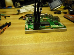
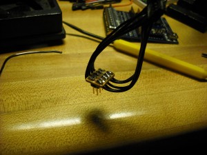
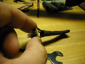
This is a shot of the connectors standing out of the Dockstar. Since I had four connectors with 3 pins each, this means that I had two pins that hung over the connector block on the Dockstar. Since these two wires were not needed, I cut them and removed the metal connector from inside the plastic, leaving 10 wires for 10 pins of the dockstar’s JTAG port. We’ll deal with the two vacant holes later.
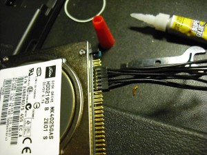
Little known fact: The pin spacing on the Dockstar’s JTAG port is identical to that of a laptop hard drive (which is why this part of the process is optional.) In a pinch, you can use a laptop IDE adapter similar to this one (in fact I own several exactly like this). If you decide to use a laptop IDE adapter, use the part of the adapter opposite the power connector.
Since the goal is to harden the four little connectors to one single connector, I used a dead laptop hard drive and superglued the four connectors together. USE THE SUPERGLUE SPARINGLY!! You do not want to superglue your connectors to a hard drive so only put a tiny amount. It also helps to put a dab of glue on one connector, then put the connectors together as you’re pushing them onto the laptop HD pins. Make sure they are completely seated so they will be even as possible. If you see the pins of the laptop HD, you’re not down far enough.
Once you get all four connectors onto the laptop HD and properly aligned, let it cure for at least an hour. This will ensure that the superglue bonds correctly and the connector doesn’t fall apart later.
Now that the superglue has set, check that it still fits in the Dockstar. On the connectors used here, my wires were quite long. To alleviate yet another mass of cable snakes on my desk, I cut them down to about three inches, which should be big enough to handle, but small enough to not get in the way. You can cut your wires to any length desired.
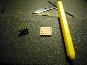
In order to solder to the 10 pin header and ensure that the wires would not seperate from use, I chose to use a small piece of PCB as shown below.
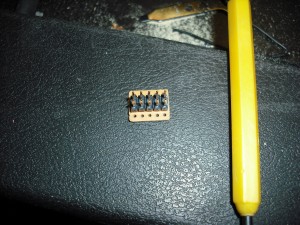
Keep in mind that if you cut your own, you’re soldering 10 wires into a 10 pin header, so you will need a 20 hole piece of PCB (5 holes by 4 holes). The idea here is that the wires will come in on the component side of the PCB and wrap around it then go further down to the 2.0mm connector we just glued together. Go ahead and solder the header into the center two rows of the PCB as shown below(Leave one row of 5 on each side of the header).
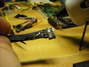
Strip off a 1/8 inch off of each wire on one side of the glued connector and solder to the PCB. Keep your pinout the same and do not cross the wires. Below, you can see that the first half of the PCB and the wires has been soldered.
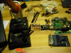
Now comes the fun part. Trying to solder the other side of the PCB without burning yourself or the other wires and without creating unnecessary solder bridges to other pins. Below is a shot of my connector, partially soldered.
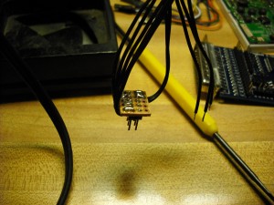
Protip: If you don’t already have a pair, I highly recommend you get a pair of Helping Hands for soldering like this. Available at Radio Shack and many other electronics outlets. Below is a picture of the completely soldered PCB.
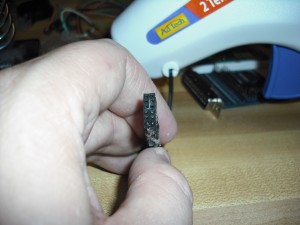
Now that the PCB is soldered, go ahead and check your wiring! Don’t do any pin swaps, make sure that pin 1 on the 2.0mm connector is pin 1 on the header, pin2 on the 2.0mm connector is pin 2 on the header and so on. Also make sure that you didn’t bridge between pins on the PCB. Before you slip on the shrinkwrap, we’re going to reinforce the body of the adapter. Get your hot glue gun ready and shoot a large bead of glue down the length of the wire. Once that is done, shoot some more hotglue around the connector to reinforce the wires coming out of the connector. Below is a picture of the hotglue process.
The hotglue on the wire-side of the plug will make sure that the wires don’t wiggle around inside the heatshrink tube and fail later on. After you’ve properly applied the hot glue, put the tip of the hotglue gun over the two holes that we vacated earlier. Keep consistent pressure on the hotglue gun and press the trigger. This will inject hot glue into the holes left behind when the excess pins were extracted and ensure that the connector is “keyed” and will prevent a one-off connection (and prevent further headache). This is what the hotglue injected connector looks like.
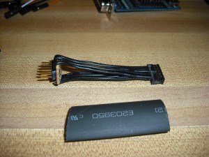
Take one moment and check your cable one last time. Make sure that the pins are wired one to one. Once you’re ready, get the heatshrink tube and cut it to a little bit less than the length of your adapter. Below, you can see the heatshrink and adapter lengths I used. (This image was taken before the hot glue was applied.)
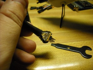
Slip over the heatshrink wrap over the connector (it may not fit over the PCB) and leave just a little bit so that it overlaps the 2MM connector end. Apply even heat to the 2MM connector end first so that it will shrink and hold the heatshrink wrap in place as you apply even heat to the rest of the connector. When completed, you should have a connector resembling the below image.
Now take the hotglue gun and fill in the gap between the heatshrink wrap and the bottom of the PCB. If your gluegun has a fine tip, also shoot some hot glue into the open end of the shrinkwrap. This will further harden the connector and ensure that it doesn’t flex and damage the connections. You may have something looking like the below image.
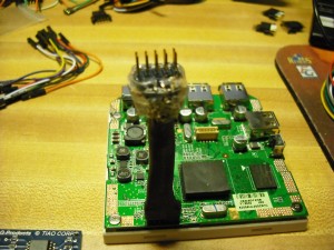
For a final touch, wrap and distribute hot glue around the wiring from a little bit over the heatshrink wrap all the way to the black part of the header wiring. It’s ok to use a large amount of glue as this will make sure that the connector is properly protected. As a last step, connect it to the Dockstar and make sure it fits. Once finished, you should have something resembling the below image.
Now, you have a completed Smokestack adapter. You can use this for any device that has 2.0MM connector pitch and for any purpose. Since the header on top is a 1 to 1 representation of the connector on bottom, you can use this anywhere where you need to use breadboard connectors for a temporary connection to these headers.
Section 2: Wiring it all up.
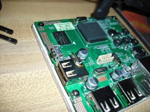
With a completed smokestack adapter, now you can wire it all up together but before we begin, it is highly recommended to solder in a ground pin. This ground pin will be used to ensure that the ground used by the JTAG adapter’s reference ground will be the same as the ground used by the Dockstar. While it may not be required, it is recommended as a difference in ground may end up corrupting data being sent and received as part of the update. To do that, we can use any of the ground planes, shields or open spots on the PCB. I preferred to use one of the three USB shields as the shield’s purpose is the same as the GND connection that we are trying to establish. For this, we’ll use a jumper pin with no plastic on it. Start off by applying a small bead of solder to the USB shield as shown below.
Apply the heat from the soldering iron to the bead again and drop in the jumper pin. Remove heat and do not touch the jumper pin until the connector has cooled. Do not apply heat for a long period of time otherwise you may damage the USB port itself. Below is the completed ground pin installation:
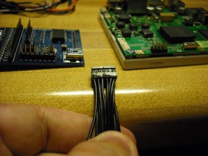
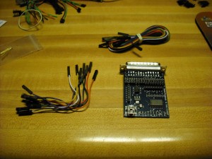
Now, we have a properly installed Ground pin that is easy to connect and remove and we also have our smokestack JTAG adapter. At this point, we can start wiring up the JTAG connector up and prepare for recovery of our dead dockstar. If you went with my suggestion and ordered the TIAO Parallel JTAG adapter, you should have received the following items. JTAG board (blue with DB25 connector), Short jumpers (left of JTAG board) and Long Jumpers (above board) as shown in the picture below.
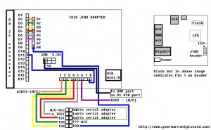
The below image is the entire wiring diagram for the Dockstar JTAG adapter. As long as you keep pin 1 on the dockstar as pin 1 on the smokestack adapter, you should have no problems with the connection. As mrbill and Klingon and several others pointed out in the PlugApps forums, the nSRST line (orange) and the DINT(purple) leads are both not connected. Pin 1 on the Dockstar/Smokestack are also left unconnected as we will use the Dockstar’s power supply to power the board while it is connected to the JTAG adapter. Additionally, it is crucial to plug the USB cable into the JTAG adapter and into a PC to power the onboard buffer chip. Without the USB cable connected, the adapter will not function. There is also an LED on the JTAG adapter that will light when the device has sufficient power. Click on the below image to get a much larger image.
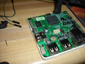
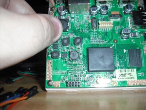
The Dockstar layout diagram on the right hand side of the image is bundled together to provide a reference. Pin 1 of the JTAG port is on the LED side of the jumper and is towards the center of the board and is designated by a black dot in the image and a white triangle on the dockstar board itself as shown below. The picture of the Dockstar is rotated 90 degrees clockwise to the layout diagram in the image above.
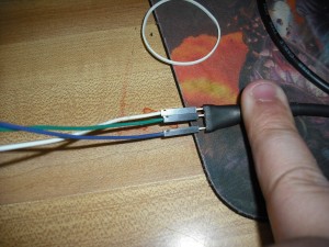
You can use the following images as a reference that your dockstar is connected properly. The below image is a picture of my CA-42 adapter’s serial header as discussed in the serial port post. Also, since the serial port post discussed soldering to the header, if you haven’t done so already, remove the existing serial port wires so that your smokestack adapter will fit. In the image below, the three jumpers coming off of the pins are colored as they would be if you had just cut and stripped back the CA-42’s cable. Remember that your CA-42 cable may be different!
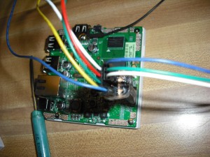
The below image shows the top of the smokestack adapter and the respective colors. You can see that the black wire for GND is attached to the USB shield pin we installed earlier. Remember, pin 1 and pin 7 on the smokestack are left not connected!
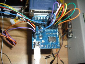
The below image shows the JTAG adapter, properly wired and ready to go. You can see the device is powered by the USB connector and that the orange and purple wires have been spared off. Although the flash from my camera drowned out the red power LED, you will need to make sure that your LED is lit. Please note, the JTAG adapter does require power however it will not show up as anything in Windows as we are using the USB port strictly for the power lines for the JTAG buffer.
An aerial view of the whole mess. 😛 Yes, I know my desk is still messy.
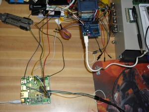
Wow, what a rats nest.
Now that all of the required connections have been made, it’s time to get busy with the software. Plug in the power cable to your dockstar and proceed to the next section.
Step III: Software
If you haven’t already, go back up to the Parts list and download Kragorn’s dockstar.cfg, OpenOCD and the uBoot image.
Install the OpenOCD software and accept the defaults. Once completed, unzip the dockstar.zip and copy dockstar.cfg to C:\Program Files\OpenOCD\0.4.0\board and then copy your uboot image to C:\Program Files\OpenOCD\0.4.0 It would be recommended to rename it to just “uboot.bin” so that way you won’t have to retype that complicated line later on.
Now that we have all the proper software in place let’s discuss what all is going to happen. When you start OpenOCD in a DOS window, it will in turn start a telnet server on localhost, port 4444. You will use PuTTY to connect to the telnet server process and issue commands to OpenOCD. In conjunction with that, you will need a second PuTTY session established to COM1 (if your windows machine has the CA-42 cable plugged into it) or to SSH to the machine you have the cable connected to. The reason is that once you enter specific commands on the telnet window, you need visibility to the other window (serial or SSH) to see if your dockstar is booting. Timing is critical! From here on out, commands and things to look for in output are in bold with other important text in bold, italics and underline.
In my configuration, my windows computer is what will run OpenOCD and the telnet session, and a nearby Linux box will have the SSH session with an application called minicom.
Start off by opening a DOS window (Start -> Run -> “cmd” )
Type the following command in exactly as shown:
openocd -f board/dockstar.cfg
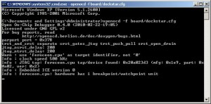
You should get output similar to the below image. If you get what I have, then you can proceed to the next step. If you get any errors, check your wiring. Make sure only those pins shown in the above images are what you have hooked up. Also, you may get a Windows Firewall exception error. If you do, just hit “Allow” otherwise you won’t be able to talk to OpenOCD.
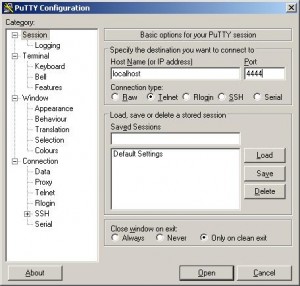
If OpenOCD is running without errors, minimize the DOS box and start PuTTY. Use the below configuration to establish a connection to the telnet process that OpenOCD started.
When you connect, you should get a window that says “Open On-Chip Debugger” with a caret “>” prompt. Before we continue, if you haven’t already pulled up your serial session to the dockstar, you will need to do that now. The issue is that from here on out, we will either be communicating with OpenOCD via Telnet, or communicating with the Dockstar via serial.
Now that you’ve established your connection to OpenOCD, perform the next two steps.
- Type the command “init” into the telnet session and hit enter.
- Type the command “sheevaplug_init” into the telnet session and hit enter.
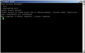
Now, here is the hard part. The routine sheevaplug_init from above will attempt to halt the processor. The Marvell chip has two types of halt, one of which labelled “ARM” and one labelled “Thumb”. If your output resembles the below output (processor halted in Thumb state), you will need to perform the next steps otherwise skip down to the next section. When in doubt, continue with the instructions below.
If you got “Target halted in Thumb State”: There is some additional trickery that must be performed. The issue is that the processor must be halted in ARM state as this allows OpenOCD to communicate with the processor properly.
- Hit Ctrl-C in your OpenOCD session. Your PuTTY session will break and generate an error. Dismiss the error and restart OpenOCD.
- Hold down the reset button and keep it held down with one hand and with the other, type “sheevaplug_init” and hit enter. Ignore the error messages.
- Type in the command “halt” . DO NOT HIT ENTER YET!
- Release the RESET switch and simultaneously hit Enter.
- You should see that the processor was halted in ARM state.
- Type in “sheevaplug_init” and hit enter. No output should be generated from this command.
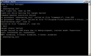
Check your telnet session output with my output in the screenshot below. Make sure your output matches the screenshot before proceeding.
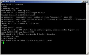
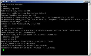
Now for the ultimate test. We need to probe the NAND flash to make sure that the processor can communicate with it. Type in “nand probe 0” (zero) and hit enter. If everything is correct, you should get text returned similar to “NAND flash device ‘NAND 256MiB 3,3V 8-bit’ found“. If you get any other message ESPECIALLY anything about Unknown Manufacturer, restart OpenOCD and try again. Here is my output so far:
Now that the processor has been correctly identified by OpenOCD and the processor has properly identified the flash memory, we can now load the image into the Dockstar’s RAM and tell the processor to execute it. Type in load_image uboot.bin 0x800000 (zero, letter x, 8 and five zeros). If you renamed your uboot file something other than “uboot.bin” then substitute as needed. This will take a couple of minutes as the image is transferred. Here is the output of what I have after the image loaded into RAM:
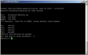
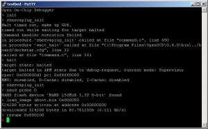
When you get the caret prompt back “>”, type in the command “resume 0x800200” and check your serial connection for activity. At this point, you can minimize the telnet session. Now we will be dealing expressly with the serial connection. Depending on your connection method, you may have a different window, but the text is the same. As soon as you hit enter on the resume command, you should notice that the LED on your once dead dockstar is now blinking. Immediately switch over to the serial connection and hit a key to disrupt the boot process. If you did it right, you should see that the command prompt now shows Marvell>> as shown in the screenshot below:
DO NOT DISCONNECT POWER FROM THE DOCKSTAR YET! WE ARE NOT DONE. The Dockstar has successfully loaded and ran the uboot commands in RAM however if we hit the reset switch or powercycle the dockstar, the device will return to it’s zombie state, and we will have to do it all over again. The only thing left to do is to prepare and write the image to flash.
If you were like me and you accidentally typed in ‘nand erase” and bricked your dockstar, you will need to re-erase the flash to reload it. If you bricked your dockstar by another method, skip this step and go on to the next paragraph. To do this, type in “nand erase“. This will erase the entire flash chip. Now to write the working uboot to flash, use the command “nand write.e 0x800000 0x0 0x80000” (zero x eight then 5 zeroes, zero x zero, then zero x eight then four zeros). You should get a message that the nand write was successful similar to the below screenshot.
If you did not brick your dockstar by an errant nand erase command, you will want to use “nand erase 0 0x0 0xa0000” (zero, zero x zero, zero x a then four zeros). The reason for this difference is that if you didn’t erase your flash, this command will preserve the u-boot environment variables, otherwise you would have to recreate them later on.
Now, it’s time for the moment of truth. Don’t start disconnecting wires just yet, simply tap the reset switch to load the uboot from the flash and test your recovery. You will notice two key things: Your uboot will be stuck in a permanent loop (assuming you didn’t interrupt autoboot) and the LED on the dockstar will alternate between flashing green and flashing orange as uboot cycles through. This is because the dockstar can’t find a valid kernel or filesystem to boot from. If you used the same version of the uBoot I listed above then you will notice that this uboot will attempt to boot off of USB key drives unlike the original factory image which opens up a LOT of opportunity. 🙂
To clean up, simply exit the various windows you have open, and exit OpenOCD by hitting Ctrl-C. Remove power from the Dockstar, then remove the smokestack adapter and the ground wire on the USB shield. If you want to make sure (because you’re as paranoid as I am, reapply power after all the jumpers have been removed and make sure that the Dockstar’s LED continues to blink orange then blinks green and repeats. This means that your dockstar is confirmed as running off it’s own flash.
Now get to hacking!
Section IV: Notes and Credits
This article was assembled using information and help from various sources. I want to thank everyone listed below for your assistance in helping me with getting the Dockstar JTAG figured out. It was definitely not easy for someone new to JTAG however it was an enjoyable learning experience once I got the bugs worked out, even if I did scratch my head a lot.
From the PlugApps forums, I’d like to thank Admin, Kragorn, bzboi, klingon, ygator, mrbill, and jtagfun.
A special thanks to bzboi for the initial howto that most of the OpenOCD instructions were used from and to Admin for the starting post with the Dockstar’s JTAG diagram.
I’d also like to thank mrbill for getting me involved with these things. It’s all his fault that I even have a dockstar to break. 😛
Thanks goes to Kragorn for finding out the proper settings in his dockstar.cfg so that all of us could unbrick after the inevitable “Oops…” moment.
Last, but not least, thanks goes out to Jeff Doozan for his work with uBoot and compiling in needed features into the bootloader so that we can use USB sticks as boot devices.
Where do we go from here?
The answer is “Where do you want to go?” In my relatively short time with the Dockstar, I was working on getting OpenWRT compiled and installed on it. OpenWRT is the same OS that they use for the Linksys and other branded routers and is pretty much it’s own distribution. There are also processes on how to install Debian onto the dockstar, using a laptop drive and USB sled to run the OS. There is a lot of people doing research and finding out other warranty voiding things to do with their dockstars so take a look around.
As far as me personally? I have three of them and while one of them is going to be a small NAS fileserver, one of the more esoteric things I was planning on doing with mine is making it into a roving USB camera with wifi. The idea is that the Dockstar’s mainboard would be the brains of the rover and could send commands to a Parallax BOE-BOT via a usb to serial converter. Since the entire thing would be wireless off of a USB dongle, I could use the IP based connection to deliver video and commands via a custom written application.
I sincerely hope that you are able to recover your dockstar using the above process. It’s no fun when you accidentally destroy something you have put so much work into however now you should be able to work on the Dockstar without fear that you’re going to damage it and prevent it from booting. Also, if you decide to try custom boot loaders, you can do so worry free.
Happy Hacking!
FIRESTORM_v1
26 Comments for this entry
2 Trackbacks / Pingbacks for this entry
-
Revive a DockStar and get so much more - Hack a Day
September 9th, 2010 on 8:27 am[…] has done a fabulous writeup on not only resurrecting his dead DockStar with JTAG, but also includes some handy techniques and useful information that could be used with other […]

September 9th, 2010 on 9:57 am
Thanks, very helpful blog entry.
My only nit is that you seem to be terminally confused about the difference between “its” and “it’s”. 😛
September 9th, 2010 on 6:20 pm
I started a new section in my forum as a place to discuss dockstar hacking 🙂
check it out http://jertechonline.com/forum/viewforum.php?f=16
If you like I might be able to setup a wiki to formally document more information 🙂
October 1st, 2010 on 10:39 am
Awesome stuff, I’m excited to get my Dockstar in the mail. I’m curious about getting into working with JTAG, how did you begin?
Maybe a possible future blog post or series of posts could be a JTAG primer?
October 7th, 2010 on 1:01 pm
Great howto, I had to follow it and got my dockstar back to live. Thanks.
But…
your “A copy of the Jeff Doozan’s custom USB-boot capable u-boot (Recommended!) (Mirrored Here)” points to a file named uboot-original-mtd0.kwb and that’s the original uboot and not the custom by Jeff (uboot.mtd.kwb).
So you can’t boot usb drives after flashing.
And regarding the “thumb state” timing stuff: it’s much more comfortable to write the “sheevaplug_init” with both hands and hold the reset button down just before hitting enter. 🙂
October 25th, 2010 on 10:50 pm
That’s weird that you mention it, It’s quite possible I got my inages mixed up. All I know was that initially, my DS wouldn’t even try to find a USB stick if the kernel was not able to be mounted from the flash. After I used Jeff Doozan’s uboot, I noticed that it would then attempt to find the USB stick (even though mine was not bootable) after booting from flash failed.
As soon as I get my stuff unpacked and get back into my hacking groove, I’ll take a look at it again and update the images.
FIRESTORM_v1
October 25th, 2010 on 10:59 pm
Hello Eod:
Honestly, I hadn’t even needed to come across the subject of JTAG until I bricked my dockstar. I consider myself fortunate considering that I’ve shived DD-WRT and OpenWRT into some impossible devices but never needed to find JTAG details until I blew up my dockstar.
JTAG is used most commonly by OEM providers to burn their own custom software into the device before it goes to QA and production. It’s faster to use JTAG on a quick disconnect (usually a pin header or solder pads) that supplies the minimum voltage to get the processor and the flash ROM and RAM to fire up than it is to hook up a power supply, network cable and serial cable in order to tell the device to get the firmware. JTAG supplies the needed voltages and signallings to get the device to fire up without requiring the software on the chip first.
A friend of mine who is an actual engineer told me that it was a lot more to do with curbing piracy. He described it like this:
You design a device with certain hardware and certain software
You send the hardware spec, parts list and PCB layout overseas to get it built en masse.
You set up the software so that it’s ready to be burned to the hardware when it returns from the overseas fab house.
You run the device post-burn through QA, reject the bad ones/repair them, then push it out.
The idea is that you maintain the software at all times and only outsource the hardware. This way, someone at the fab house can only steal the hardware design but don’t have the software to do a thing with it.
(Now keep in mind, that’s not my theory, just my engineer friend, however it does make a lot of sense…)
FIRESTORM_v1
March 8th, 2011 on 4:54 am
Hi,
I need help. I followed all the process, but still got an issue :
– When all the 3 wires are plugged, I then plugged the power, and the LED don’t blink. If I remove the GND wire, LED start blinking.
I’ve make it again, and again, without any success ?
Any idea …
I have 2 bricked DockStar + one I used for my home hosted blog : http://www.it-wars.com
Thank’s
March 22nd, 2011 on 10:32 am
Hello Vincent:
Check that you’re not connecting to the VCC line on the dockstar’s JTAG port. With the DS board oriented so that the LED is facing you, the GND, TX and RX pins are on the frontmost row of the header with GND being towards the LED. If you are plugged into the second row of pins, you may be inadvertently shorting VCC to the GND pin of your serial adapter and causing the whole thing to halt.
If you can, give me a picture of your connection (unpowered, but connected up) and I’ll take a look and see if I can see what the issue is.
FIRESTORM_v1
May 26th, 2011 on 8:30 am
Thanx – another bricked Dockstar back to life! I’d been putting it off for a while but bit the bullet.
The command nand erase 0 0x0 0xa0000 should be
nand erase 0x0 0xa00000 methinks
July 24th, 2011 on 6:03 am
Can’t get it halt….
Always got something like this:
Halt timed out, wake up GDB.
timed out while waiting for target halted
Command handler execution failed
in procedure ‘halt’ called at file “command.c”, line 650
called at file “command.c”, line 361
July 24th, 2011 on 6:05 am
Can not halt it… always got something like this:
Halt timed out, wake up GDB.
timed out while waiting for target halted
Command handler execution failed
in procedure ‘halt’ called at file “command.c”, line 650
called at file “command.c”, line 361
September 14th, 2011 on 8:39 am
I had 2 dockstar dead, now I have 2 dockstar alive. Great job!
Someone can explain me why after load u-boot in ram at 0x800000 we need to resume 0x800200 and not resume 0x800000 ?
September 16th, 2011 on 1:44 am
Hi,
i got a dead dockstar (dead while playing with serial when i m flashing its bootloader).
I got all the above mentioned stuff and have all set up, but when i execute the mentioned command
openocd -f /board/dockstar.cfg
i get the below message output;
Open On-Chip Debugger 0.4.0 (2010-02-22-19:05)
Licensed under GNU GPL v2
For bug reports, read
http://openocd.berlios.de/doc/doxygen/bugs.html
parport port = 0x378
trst_and_srst separate srst_gates_jtag trst_push_pull srst_open_drain
jtag_nsrst_delay: 200
jtag_ntrst_delay: 200
Warn : use ‘feroceon.cpu’ as target identifier, not ‘0’
Error: missing privileges for direct i/o
Command handler execution failed
Do we need any kind of drivers ?
October 17th, 2011 on 8:10 pm
Hello Kanishk:
That’s a good question, I didn’t encounter that error when I ran it. I was using Windows XP as Administrator. What is the OS version that you’re using and do you have root/administrator privileges?
FIRESTORM_v1
October 17th, 2011 on 8:12 pm
Hello JeanMi2Lyon:
I believe that the 200 bytes are used to store the “default” u-boot parameters in RAM. When you’re flashing to the chip, that same offset is observed when writing the image so as to not overwrite any predefined u-boot parameters that are configured. In my case, I had erased the flash chip, so I had to manually redefine the u-boot parameters and commit them to flash.
FIRESTORM_v1
May 9th, 2012 on 10:28 pm
http://www.logicsupply.com/products/ph_adapter
skip the smokestack adapter and get straight to the jtag fun…
May 26th, 2012 on 11:31 am
Hi firestorm,
I have resurrected my dead DockStar. Thanks for this instruction.
But now I have the problem to install the OS in the USB-Stick.
Could you tell me how to install a Debian Squeeze on an USB-Stick only with the bootloader on the DockStar?
Thanks in advance
Robert
June 6th, 2012 on 1:29 pm
Hello Christineedadrink:
That is an awesome find! When I initially started on this project, I could not find any adapter suitable for the Dockstar so the smokestack was a necessity. This adapter is exactly what I was looking for and would negate the need to build an adapter.
Thank you!
FIRESTORM_v1
June 24th, 2012 on 3:15 pm
There’s also this adapter:
http://pcpartsandcables.com/product_info.php?cPath=34&products_id=103
Kind of looks like the one you’ve built. 🙂
I’ll give you it wasn’t easy to find…
June 30th, 2012 on 8:35 am
Thanks a lot for this howto ! I succesfully resurrected my dockstar, too.
Some things to mention: If you get JTAG access and start the loaded image, you have to press enter in the serial conenction _immediately_ !! i was letting the dockstar reset itself in the uboot environment some time, until i could switch my BPv3 to the serial lines – this does not work! You can type all those nand erase, nand write.e .. stuff – the dockstar wont start if you powercycle !
You need a seperate RS232 serial converter !
@JeanMi2Lyon: The extra 200 bytes contain the kwb header, as far as i understood. Its initially placed at offset 0x800200.
July 23rd, 2012 on 11:09 am
Hello Christian:
I tried for two weeks to find these pitch adapters however the only option at the time was using a 3.5 to 2.5 Laptop HDD adapter and mine were wired wrong. I had to build my own. Thankfully, the parts are accessible now should I ever need another adapter. Thanks for the link.
FIRESTORM_v1
July 23rd, 2012 on 11:57 am
Hello r_knipp:
Honestly, it’s been a while since I’ve done anything with the Dockstar, I can’t remember what process I used. I do remember this page by Jeff Doozan who took the time to create some useful scripts on how to do it. This assumes that you are able to ssh to the device’s default installation and are able to run the scripts provided: http://projects.doozan.com/debian/. I’ll have to see if I can find my dockstar equipment and start hacking on it again.
FIRESTORM_v1
February 17th, 2013 on 2:45 pm
finally it is alive 🙂 Thank You
About the JTAG connection, for me worked this (you dont need need to connect pin 2 on parallel port)
So all you need is 5pcs of 100ohm resistors some wires and parallel connector
http://wiki.openwrt.org/lib/exe/fetch.php?media=http%3A%2F%2Fwww.lan23.ru%2Fwifi%2FJTag%2Fpost-1-1224568532.gif
February 28th, 2013 on 3:32 pm
Hello Bladde:
Glad to hear that it worked for you! I believe that the pin 2 (SRST) was disconnected (orange lead) for this. The mapping is from Pin2 off the printer port, to A1 then Pin 1 on the output header (after the level shifter) is disconnected. Generally, Pin 2 (Printer) would go to S_RST and is used in some implementations as a software reset button for a device under JTAG testing.
Have fun!
FIRESTORM_v1
May 9th, 2013 on 3:48 am
Hi
I connected the JTAG TIAO as described on latpie Dell D430 Windows 7 and Windows XP virtual machine port is LPT1.
Jtag connected to LPT1 and USB power supply for Jtag seen.
The LED on the Dockstar does not light up.
When you start OpenOCD I got the following error:
Open On-Chip Debugger 0.4.0 (2010-02-22-19:05)
Licensed under the GNU GPL v2
For bug reports, read
http://openocd.berlios.de/doc/doxygen/bugs.html
parport port = 0x378
trst_and_srst separate srst_gates_jtag trst_push_pull srst_open_drain
jtag_nsrst_delay 200
jtag_ntrst_delay 200
Warn: use ‘feroceon.cpu’ as target identifier, not ‘0 ‘
Info: clock speed 500 kHz
Error: JTAG scan chain interrogation failed: all Zeroes
Error: Check JTAG interface, timings, target power, etc..
Error: JTAG scan chain interrogation failed: all Zeroes
Error: Check JTAG interface, timings, target power, etc..
Command handler execution failed
Warn: jtag initialization failed, try ‘jtag init’ again.
What am I doing wrong?
July 18th, 2013 on 1:38 pm
That is an odd one. I don’t think I have ever had any luck with a virtualized LPT port. Since OpenOCD does a lot of low-level stuff with the port in regards to signalling, it’s best to use a Windows XP computer run on the bare metal as opposed to using a virtual machine. Do you have another machine with Windows XP and a hardware parallel port that you could use to reflash your Dockstar?
Good Luck!
FIRESTORM_v1