Hardware: Remote Control your Arduino
by firestorm_v1 on Jul.10, 2012, under Hardware, How-To's, Microcontrollers
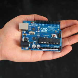
Have a giant Arduino powered killbot, but can’t fancy being right next to it when you unleash it on the unsuspecting populace? Want to change the mood-lights in your dorm without having to get up off the couch? Why not use IR remote controls to do the walking for you? In this article, I will be covering how to use the IRremote Library written by Ken Shirriff for the Arduino to control a seven segment display as a proof of concept. Killbot not included.
A bit on IR remotes:
Infrared remote controls work off the premise of modulation of a signal which is then demodulated and interpreted by the receiving unit, be it the TV, a cable box, or other device. When you hit a key on your remote, the remote’s microcontroller senses the keypress and then sends a code corresponding to that keypress to the receiver by way of an infrared LED. The destination device on the other end receives the infrared light pulses and then translates that into a code that then performs an action such as turning off the TV or changing the channel, etc.
In order to prevent one remote from turning on ALL of your appliances with line of sight to the remote, different protocols are used. This also helps to minimize infrared interference being received from other light sources like incandescent bulbs and the sun. For example, you have a Sony TV and a Motorola cable box, with a JVC DVD player. When you hit the power button on the Sony remote, the TV sees the Sony protocol and decodes the power button then turns on the TV. The JVC DVD player and the Motorola cable box disregard the pulses as noise and no action is taken. Similarly, if you have a Sony remote and you go to the Sony TV store and hit the power button on the remote, you’re likely to get thrown out of the store as you will have turned off all their TVs. (Not recommended. ) For more information on the protocols and theory behind Remote Controls, please take a look at http://www.sbprojects.com/knowledge/ir/index.php
Universal Remotes:
The whole device specific protocol does make the use of a remote a lot easier however if you have many devices (like an AV cabinet with a VCR, DVD player, Blu-ray, Sound System, CD changer and a video streamer), your coffee table can quickly be overrun with remote controls. The cure-all to this is a universal remote which can be programmed to control specific devices. Using our earlier example, it can control your Sony TV, JVC DVD player and Motorola cable box by using function keys to switch which codes the remote sends out. Universal remotes are a godsend when working with microcontrollers as you can then set the remote to the Sony protocol, arguably one of the most well documented protocols to date.
Getting Started:
In this how-to, we will be using the IRremote Library for the Arduino to test our remote, get the key codes for the keys we want to use, and finally testing it out with lighting up a seven segment LED display. You will need the following items:
- An Arduino (I use an Arduino Uno
- Breadboard (any size)
- A USB A-B cable for the Arduino
- Jumper wires
- A three pin IR receiver module like this one from Sparkfun
- An IR remote control (If you don’t have a receiver or a remote control, I recommend using this kit instead as it comes with everything you need.)
- A seven segment LED display (common cathode or – )
- A 74HC595 shift register
- Seven 220 ohm resistors (Red – Red – Brown)
- An LED (any color)
- (Optional) A camera with an LCD preview screen or camera phone.
- (Optional) A breadboard power supply ( I recommend this one ) If you don’t have one, you can use the Arduino’s 5V pin.
- A PC with the Arduino software pre-loaded and operational.
Let’s get to testing.
Test the remote control
In this test, we will do a basic check to ensure our IR remote works. Nothing sucks worse than going through a howto wondering why it’s not working only to find out that a part’s busted. Turn on your camera and point your IR remote at it then press a key on your remote. You should see something flashing in the front of the remote. If you do, then the remote works and you can proceed with confidence. If you don’t, check some other keys and replace the batteries in the remote just to be on the safe side. You don’t have to take a picture of the remote to be able to see the IR light coming out of the remote. In some remotes it may show up red and in others it may be purple. If you have a remote that has multiple IR LEDs in the front, you may get a lot of white light. My remote is a “mini” remote control and the IR LED is visible on the front. In the picture below, I am holding down the POWER button, and you can see by the purple light that my remote is working.
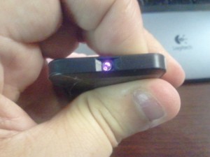
If your camera doesn’t show the flashing LED and you replaced the batteries on it, try another camera or see if the remote operates the device it is supposed to work with. Some cameras have an IR blocking film on the lens which will not allow the IR from the LED through. Cameras in cellphones usually do not have this film.
Testing the IR receiver
Now we know that the IR remote works, it’s time to test the IR receiver. You will need to check your receiver’s datasheet to be sure however most three-wire IR receivers use the same wiring method. With the bulb (curved part) of the receiver facing you, the left most pin is signal out. The middle pin is Ground (Vss) and the rightmost pin is +5V (Vcc) Set up your breadboard like the image below. The right pin should go to your power rail on your breadboard, the middle pin should go to the ground rail on your breadboard. The left pin goes to a resistor which goes to the cathode side (look for the flat part) of the LED while the anode side should go to your power rail. Look at the image below for layout.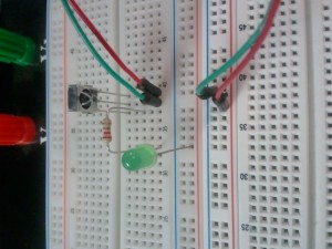
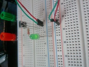
Now for the moment of truth. Turn on your power supply and the LED should stay off. Point your remote control at the receiver and press a button. The LED should blink rapidly as long as you hold down the button. If it does not, shut off your power supply and check your connections. In the image below, the LED is lit up however it was flashing when I took the image.
Importing the Library
Now that we have determined that the remote and the IR receiver work, it’s time to get the IR library. Head over to Ken Shirriff’s Blog and download the IRremote.zip file. Look for the link under the image of the Arduino and Remote.
When you download the file, extract it and you should have a directory called “IRremote”. You will want to copy this into your Libraries directory for the Arduino program:
- Windows users: Copy the directory into arduino-XXXX/Libraries (wherever you have copied the Arduino directory to). Since mine’s on the Desktop, it’s Desktop/Arduino-2200/Libraries.
- Linux users: Copy the directory into /usr/share/arduino/libraries
- Mac users: I don’t know. If you figure it out, drop me a comment and I’ll add it here.
Connecting Hardware and getting your key codes
Now that the library is imported, we need to hook up the IR receiver to the Arduino so we can read the codes for our remote. If you haven’t already done so, bridge the +5V and the GND lines from the Arduino over to your breadboard, then hook up the center pin of the IR receiver to the GND rail and the right most pin to the +5V rail pretty much like we had it connected for testing. Instead of using a resistor and LED for the output pin, we will connect a jumper from the output pin to pin 11 of the Arduino. Use the above images as a guide.
Load the example code from File -> Examples -> IRremote -> IRrecvDemo then click the “Upload” button. (second from the rightmost icon on the toolbar). This will push the code to the Arduino.
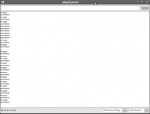
Click the “Serial Monitor” button to bring up a window that will allow us to see the codes being returned to us by the Arduino. Start mashing buttons and you should see a lot of numbers scroll by like in the image below.
In the above screenshot (click for larger image), you can see several codes. The ones that start off with FF and then have numbers or letters are the codes we are after. A FFFFFFFF is a continuation code and the 0 on its own line is a read error. This code will spit out the hex value of the protocol being used by your remote for the button you pressed. It is recommended to “map out” all the buttons you plan on using for your project and write them down.
My remote has a total of 21 buttons however I am only interested in the keypad buttons (0-9) and power. In case anyone else has this same remote, here are the hex values for my remote (generic chinese knockoff, model number YK-001 ).
- POWER – FFA25D
- MODE – FF629D
- MUTE – FFE21D
- PREV – FF22DD
- NEXT – FF02FD
- PAUSE – FFC23D
- VOL – – FFE01F
- VOL + – FFA857
- EQ – FF906F
- Digit 0 – FF6897
- 100+ – FF9867
- Go Back – FFB04F
- Digit 1 – FF30CF
- Digit 2 – FF18E7
- Digit 3 – FF7A85
- Digit 4 – FF10EF
- Digit 5 – FF38C7
- Digit 6 – FF5AA5
- Digit 7 – FF42BD
- Digit 8 – FF4AB5
- Digit 9 – FF52AD
Your values will probably differ from what I’ve listed above.
Now for something fun
Moar Hardware!
Once we have obtained our key codes, we can then set about to do something with it. As an example, we will be using the 74HC595 shift register and the seven segment display to light up the corresponding digit when we press a key on the remote. For those of you that have never used a shift register, it is a well known chip that allows you to use the arduino command shiftOut to send a sequence to the 74HC595 which will then show that sequence via the eight pins that form its output port. For example, sending it “01001001” would cause the 595’s output pins 1,4 and 7 to go into a high state. The advantage is that the shift register only requires three lines from the Arduino in order to be able to control 8 lines on the 595 making it an easy way to expand the Arduino’s limited pins. For more details about daisy chaining the 74HC595, check out http://bildr.org/2011/02/74hc595/ which describes the 74HC595 in detail. Below is a schematic diagram of a 74HC595.
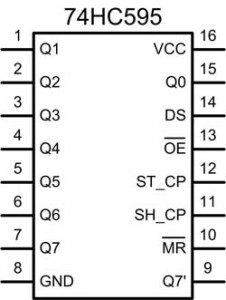
In order to connect the shift register to the Arduino, we will use pin 14 (Data), pin 12 (Latch) and pin 11 (Clock). The output port (q0-q7, pin 15 and pins 1-7) are what we will hook up to the LED display. The Reset line (pin 10) must be connected to +5V in order for the chip to work and the output pin (Pin 13) should be sent to ground. Your board will turn into a spaghetti bowl, however it will be worth it when the project is complete.

7 segment LED display
This is the pinout of a seven segment LED display. (Editor’s Note: This is a common anode display. This project calls for a common cathode display. I apologize for the wrong image.) Since the shift register has 8 output pins and the seven segment LED only has seven, (not counting the decimal point), we will be hooking up the pins one-to-one starting with Q0. In the above two images, Q0 will go to element “a”, Q1 will go to element “b” and so on. We will not be using Q7 or the decimal point, so you can allow these to float (not connected). Between each of the 74HC595 output pins and the pins of the 7segment LED display, we will need to add a 220 ohm resistor. This will ensure that neither the 595 nor the LED display are damaged from overcurrent. Because there are many different styles of LED displays with varying pinouts, I did not show my configuration however there are pictures below.
Moar Software!
With the hardware defined, we need to know what to shift out to the 595 in order to light the segments. Since the 74HC595 works in binary but we are allowed to shift out a decimal number thanks to the arduino, the number to shift out is something that can be solved with some quick math. This method of calculation applies to any device using a shift register, not just for this project so it may come in handy later on. Each element has a value assigned to it that will light it. “A” for example (top center) has the value of “1” while element “G” (center) has a value of 64 which gives us the following chart:
- A = 1
- B = 2
- C = 4
- D = 8
- E = 16
- F = 32
- G = 64
In order to form the characters we want, we have to come up with a “truth table” This table shows how we convert each number into a desired format, then convert that format into the elements desired, then we get the values we need to light the segments we want. Below is the truth table for this project:
- (Triple dash) = Elements a,g,d = 1+64+8 = 73
- 0 = a,b,c,d,e,f = 1+2+4+8+16+32 = 63
- 1 = b, c = 2+4 = 6
- 2 = a, b, d, e, g = 1+2+8+16+64 = 91
- 3 = a,b,c,d,g = 1+2+4+8+64 = 79
- 4 = b,c,f,g = 2+4+32+64 = 102
- 5=a,c,d,f,g = 1+4+6+32+64 = 109
- 6=a,c,d,e,f,g = 1+4+8+16+32+64 = 125
- 7=a,b,c = 1+2+4 = 7
- 8=a,b,c,d,e,f,g = 1+2+4+8+16+32+64 = 127
- 9=a,b,c,f,g = 1+2+3+32+64 = 103
The best way to use this truth table and the key values used earlier would be with a “switch” statement. This is computationally faster than using a nested chain of if… then statements as shown below. Copy and paste the below text into your Arduino environment and upload it.
#include <IRremote.h>

int RECV_PIN = 11;
IRrecv irrecv(RECV_PIN);
decode_results results;
int latchPin = 4;
int clkPin = 3;
int dataPin = 2;
int digit = 0;

void setup()
{
  pinMode(latchPin, OUTPUT);
  pinMode(clkPin, OUTPUT);
  pinMode(dataPin, OUTPUT);
  Serial.begin(9600);
  irrecv.enableIRIn(); // Start the receiver
  digit=73;
  digitalWrite(latchPin, LOW);
  shiftOut(dataPin,clkPin,MSBFIRST,digit);
  digitalWrite(latchPin, HIGH);
}

void loop() {
  if (irrecv.decode(&results)) {
    switch (results.value)  {
      case 0xFFA25D:
        digit=73;
        break;
      case 0xFF6897:
        Serial.println("DGT0");
        digit=63;
        break;
      case 0xFF30CF:
        Serial.println("DGT1");
        digit=6;
        break;
      case 0xFF18E7:
        Serial.println("DGT2");
        digit=91;
        break;
      case 0xFF7A85:
        Serial.println("DGT3");
        digit=79;
        break;
      case 0xFF10EF:
        Serial.println("DGT4");
        digit=102;
        break;
      case 0xFF38C7:
        Serial.println("DGT5");
        digit=109;
        break;
      case 0xFF5AA5:
        Serial.println("DGT6");
        digit=125;
        break;
      case 0xFF42BD:
        Serial.println("DGT7");
        digit=7;
        break;
      case 0xFF4AB5:
        Serial.println("DGT8");
        digit=127;
        break;
      case 0xFF52AD:
        Serial.println("DGT9");
        digit=111;
        break;
     }
     digitalWrite(latchPin, LOW);
     shiftOut(dataPin,clkPin,MSBFIRST,digit);
     digitalWrite(latchPin, HIGH);
  irrecv.resume(); // Receive the next value
  }
}
Once uploaded, your LED display should show the triple dash like in the image below
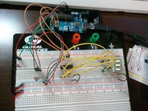
If you get the triple dash, you should be able to hit any number on the keypad and change the number on the LED display. In the below image, I’m hitting the digit 5, and the number 5 is displayed.
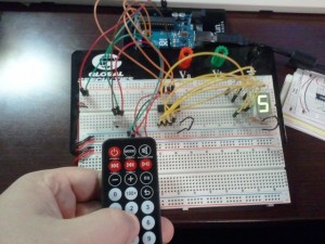
Currently, the code will allow you to hit any digit between 0 and 9 and the LED display will show the number you pressed. Pressing the POWER button will give you the triple dash again.
Troubleshooting
- If the LED display is disfigured but you get three segments lit, chances are you got two of the pins reversed. Cycle through the numbers on your remote and you should be able to identify the two pins that need to be swapped.
- If you get nothing from the LED display, check your wiring. Make sure you wired the 595 chip correctly to the LED display and to the Arduino.
- If your LEDs are extremely bright, disconnect power immediately, you have shorted the LED display straight to the +5V rail and you may blow a segment.
- If your LED display does not change from the triple dash, check your Serial Monitor and ensure that commands are being received by the Arduino.
- If you are getting readouts on the Serial Monitor but nothing on the LED display, check that the Clock, Data and Latch pins are correct on the 74HC595.
Code Analysis
The code is not very complex. Basically, it checks to see if there is any data in the results from the irrecv.decode process (included in the library) and if so, it runs the switch statement against it. If the code matches any of the case statements, it will set “digit” to that value and send out a small description of what button was pressed. At the end of the switch statement, but still inside the if.. then statement, it will shift out the resulting digit, even if it’s the same. Because of the if.. then statement, the Arduino will only shift out if there is something in the results variable and the digit will only change if the results variable matches any of the predefined case statements. This will eliminate the issue of noise interfering with the defined code values. Be sure to not specify a default result in your case statement, as you do not want to process any erroneous or noisy IR signals. The “Serial.println” statements can be removed, this is primarily a debugging and proof of concept code.
Keep in mind, after irrecv.decode has been called, you must restart the receiver by using the syntax “irrecv.resume();” otherwise your code will read once from the IR receiver and exit which would render your Arduino uncontrollable.
What to do next?
Now that you have the proof of concept and the library, you can do tons of things now. The IRremote library we used has transmission capabilities as well as receiver capabilities so you could use your Arduino to control your TV and other appliances or perhaps, you could go with the idea in the summary and build a killbot to conquer Earth. Barring that, you could always use the remote to turn on and off appliances that don’t have a remote control. Personally, I can see multiple applications, one specifically involving a light dimmer and an Arduino controlled servo. Instead of using VOL+ and VOL- for sound, it can control the lighting instead.
31 Comments for this entry
2 Trackbacks / Pingbacks for this entry
-
Using an IR remote with your Arduino - Hack a Day
July 23rd, 2012 on 7:00 am[…] remote control for a project, [firestorm] is here to help you out. He put up a great tutorial on using an IR remote to do just about anything with everyone’s favorite microcontroller […]
-
Remote Control your Arduino — Arduino Passion
July 25th, 2012 on 10:46 am[…] Find the full details here. […]
July 24th, 2012 on 7:34 am
Great tutorial! It cleared all of my doubts regarding IR devices. Perfect for beginners to understand the concept. Thank YOu!
August 19th, 2012 on 8:20 pm
Ummm, in order for the truth table to work, wouldn’t the shift register outs have to be connected to their corresponding led cathode? ie 0 outs to A, 1 to B, etc…
Just a quick question. Awesome tutorial though =)
August 23rd, 2012 on 11:25 pm
You are correct, the 74HC595’s output pins go to each of the seven segments in your LED display. For some reason, it appears that the seven segment LED pinout graphic is missing, I’ll fix this soon.
Thank you for the comment!
FIRESTORM_v1
August 23rd, 2012 on 11:40 pm
Hello OhmnioX:
When I did this project, I was in the same boat as you. I didn’t think using an IR remote would be that easy. Glad that the article was an inspiration to you.
Have fun!
FIRESTORM_v1
September 16th, 2012 on 11:49 am
Hi,
I have downloaded the IR library files. Ran the IR Receiver Dump. I have the code for my remote.
When I cut and paste your code, I get this compile error.
Any ideas on what to fix?
Thanks
C:\arduino-1.0.1-windows\arduino-1.0.1\libraries\IRremote\IRremote.cpp:943: warning: this decimal constant is unsigned only in ISO C90
In file included from C:\arduino-1.0.1-windows\arduino-1.0.1\libraries\IRremote\IRremote.cpp:22:
C:\arduino-1.0.1-windows\arduino-1.0.1\libraries\IRremote\/IRremoteInt.h:15: error: expected unqualified-id before ‘.’ token
C:\arduino-1.0.1-windows\arduino-1.0.1\libraries\IRremote\/IRremoteInt.h: In function ‘int MATCH_MARK(int, int)’:
C:\arduino-1.0.1-windows\arduino-1.0.1\libraries\IRremote\/IRremoteInt.h:178: error: ‘MATCH’ was not declared in this scope
C:\arduino-1.0.1-windows\arduino-1.0.1\libraries\IRremote\/IRremoteInt.h: In function ‘int MATCH_SPACE(int, int)’:
C:\arduino-1.0.1-windows\arduino-1.0.1\libraries\IRremote\/IRremoteInt.h:179: error: ‘MATCH’ was not declared in this scope
C:\arduino-1.0.1-windows\arduino-1.0.1\libraries\IRremote\IRremote.cpp: In member function ‘int IRrecv::getRClevel(decode_results*, int*, int*, int)’:
C:\arduino-1.0.1-windows\arduino-1.0.1\libraries\IRremote\IRremote.cpp:702: error: ‘MATCH’ was not declared in this scope
October 24th, 2012 on 9:06 pm
To add libraries to Mac OS X Mountain Lion
Go to applications, right click Arduino App, click “Show Package Contents”
Then \Contents\Resources\Java\libraries , and then add your library in this folder. After you restart the program it will be added
November 2nd, 2012 on 6:34 pm
Hello Mitch:
Thank you very much for the tip!
Firestorm_v1
November 2nd, 2012 on 6:48 pm
Hello Lynxo:
I’ll look into it again, but my code copied and pasted from the article worked. Is it possible that your browser is converting the single quotes and double quotes to smartquotes?
As a test
” should be completely vertical, not leaning to either side. (double quotes)
` points up and left. (Backtick)
‘ points straight up (Single Quote/Apostrophe)
Thank you for letting me know.
Firestorm_v1
November 8th, 2012 on 9:12 pm
Hi,
>>Mac users: I don’t know. If you figure it out, drop me a comment and I’ll add it here.
On Mac, the examples and library directory are inside the Arduino application package. Right click on the Arduino application icon, select “Show Package Content” to open it up.
I have a screen dump here:
http://dl.dropbox.com/u/219819/arduino/arduino_example_mac.jpg
Don’t link to it. It’s temporary.
Copy and use it on your server if you like.
Thx for the great tutorial.
Cheers,
Michael
November 19th, 2012 on 2:27 pm
Great Tutorial!!! I was lost until I read it!! Congrats!!
December 8th, 2012 on 7:43 pm
it did help me a lot. i’ll share it with my colleagues! thank you!
December 16th, 2012 on 8:58 am
I HAVE A SLING BOX THAT LETS ME VIEW CABLE TV ANYWHERE I HAVE ACCESS TO INTERNET VIA MY LAPTOP..
SOMETIMES I NEED TO PWR DOWN MY CABLE BOX WHEN IT GETS HUNG UP…THOUGHT I COULD SEND SIGNALS FROM VITURA IF TRANSMITTER TO HOME WHERE IT COULD DECODE AND SEND SIG TO TURN CABLE BOX POWER OFF AND ON,,,,I HAVE BEEN TRYING TO DO THIS WITH DESCRETE COMPONENTS,,IT IS DIFFICULT BUT PROGRESSING..
CAN U THINK I CAN USE ARDUINO TO ACCOMPLISH THIS MORE EASILY.. THANKS VINNY
January 14th, 2013 on 2:54 am
why do we have to use the codes that start with FF?
February 17th, 2013 on 2:36 pm
tripped over an unexpected hurdle.
gotten the arduino responding to ir codes from several different remotes around the house, and all put out hex numbers into serial monitor.
unfortunately, the arent the same numbers each time.
there are a few garbage numbers, two or three numeric figures, but i kinda expected that.
the problem is, if i press any button it will repeat said code as expected.if i release and then press and hold the same button again, then it will repeat and entirely different code. release and press a third time, and it will repeat the first code.
weird eh?
am i missing something incredibly obvious?
thanks in advance.
February 28th, 2013 on 3:35 pm
Hello Brad:
I would check for any sources of IR light (incandescant bulbs, windows, bright lights, etc). In my testing, I was doing this in a windowless room with a fluorescent light as the only other light source so it was easy for me to get the codes. You may want to check your IR receiver and make sure that it’s working right. Easiest test method would be to hook the IR receiver up to an LED and make sure the flashing is pretty consistent. You only need to capture one code without interference to get a good read.
Good Luck!
FIRESTORM_v1
February 28th, 2013 on 3:54 pm
Hello Vincent:
Your best bet would be to see be to reset the cable box by performing a powercycle on it. There is not a remote command on most cable boxes that will force the cable box to reset itself so you’ll have to build an arduino controlled switch that you can control over the Internet (or via a computer at home). It sounds like an interesting project. Let me know if you decide to do this.
Good Luck!
FIRESTORM_v1
February 28th, 2013 on 4:00 pm
Hello Bryan:
The way it was explained to me, the FF was the start of the packet, kind of an “ATTENTION” line at the beginning as a way of telling the receiver to wake up and pay attention to the next flashes of light (timing) for the packet.
FIRESTORM_v1
May 27th, 2013 on 7:38 pm
Your 7 segment diagram depicts a Common Anode but your parts list calls out a Common Cathode. Which is correct?
June 13th, 2013 on 7:55 pm
Hi. I have a remote control like yours, a chinese YK-001. What kind of batteries do you use? They say it’s CR2025, bet it doesn’t fit.wc
July 12th, 2013 on 5:26 pm
running xp, arduino uno r3. 1.03. Sensor test has led on all the time (not bright) but can detect flashing when press remote. running IRremote demo loads but gives message:
avrdude: stk500_getsync(): not in sync: resp=0x30
no codes generated in window. Using new TSOP38238 IR sensor.
Know remote working as see flashing with cell camera.
????
July 17th, 2013 on 7:02 pm
fixed problem. PC rebooted with default com port. Changed back to Arduino port # and all working ok.
July 18th, 2013 on 1:32 pm
My remote uses a CR2032, a common battery used in computers for the CMOS clock chip. The remote is pretty cheaply made and it may be possible that your “-” lead in the remote is sticking up and preventing the battery from inserting all the way in. Look in the battery slot and see if you see a small piece of metal sticking up. You may need to push it down with a toothpick then try reinserting your battery.
Good luck!
FIRESTORM_v1
July 18th, 2013 on 1:34 pm
You’re absoloutely correct. I have edited the document to reflect this. Since this shift-register will be sourcing the current for the seven segment display, the display should be a common cathode (many in, one out) as opposed to what is shown in the image, common anode (one in, many out).
Thanks for the catch!
FIRESTORM_v1
September 6th, 2013 on 11:59 pm
Hello Brad, I noticed that effect on one of my remotes. It seems that the second code is a check that the first code is correct. You may have to send the first code, wait 45ms and then send the second code for your device to work.
November 30th, 2013 on 9:05 pm
Anyone know how those ir blasters work?
They have a 3.5mm jack on the side you hook up to a pc, and then a small plastic enclosure for the ir led(s).
To generate 38khz from an audio jack, the only approach I’ve seen is to have 2 leds back to back, but is that what these commerical emitters are doing? I don’t see how they are fitting 2 leds in there!
January 24th, 2014 on 11:26 am
Hello Ben:
I have not really had an opportunity to test those IR Blasters in-depth. There are some sites that say you can generate an equivalent signal from the sound card as you indicate and there are others that say you can use the serial port to generate the same signalling. Honestly, I have not tried it.
There are commercial repeater modules, but those units are far simpler. They consist of an IR detector, signal amp (probably a transistor), and several IR or near-IR red LEDs that are in the output modules which areplaced over the IR receivers of the attached devices (tuner, TV, DVD player, etc..). When the IR detector receives a pulse, the pulse is sent to all of the IR LEDs. The device that matches the remote used to generate the IR will respond in kind. I’ve seen an incandescent light bulb and a candle cause the IR LEDs to flash, so I doubt there is any protocol or microcontroller involved in the relaying of the IR signal from the detector to all the connected output modules.
Let us know what you find out!
FIRESTORM_v1
April 30th, 2014 on 11:07 am
Its an excellant tutorial. Thank you.
I am using a HS0038 A2. 810m Infrared receiver. However the test you specified with an LED, is not working to check if its working. Kindly assist.
June 19th, 2014 on 5:34 am
nice project
how can I use the DP …..
A = 1
B = 2
C = 4
D = 8
E = 16
F = 32
G = 64
DP = 0 (zero)
or
DP = 128
one more thing what is the function of pin # 9 of 74HC595. and how can one use it
July 20th, 2014 on 2:23 pm
Hello Viki:
The Decimal Point (DP) would go to Q7 (pin 7 on the 595) and would be activated with “128”. So sending, 128+2+4 would show “1.” on your seven segment display.
Pin 9 of the 595 is an “overflow” for daisy chaining the 595’s together, e.g you would use the same three pins (Data, Latch, Clock) and send multiple codes out. The first 595 would display the first code and pass the rest down the line to be displayed by additional 595’s. If you check out http://bildr.org/2011/02/74hc595/ and scroll down to “Cascading Shift Register – AKA Chaining them together” describes this scenario quite well.
Good Luck!
FIRESTORM_v1
July 20th, 2014 on 2:30 pm
Hello Debjyoti:
Hmm, I did some research on that part and it looks like it connects up the same way as the one I used in the tutorial. I would check the following:
– Make sure you’re sending 5V and GND to the detector
– Make sure your LED is oriented correctly (maybe it’s reversed?)
– If you want to test for a bad LED, connect a voltmeter to the output pin and see if you get any voltage from it when you hit it with the remote IR light.
– (Not very likely, but worth a consideration) – is it possible that you’re using an IR remote that’s operating at a different frequency? Research on that particular receiver indicates a frequency range 800nm to 1100nm with peak response at 940nm. Frequency range is 35KHz to 41KHz with peak detection at 38KHz. You could try sticking your project outside (temporarily) as the sun produces all kinds of IR light on all frequencies. If you can’t get a light there, you may have a bad receiver.
Good luck!
FIRESTORM_v1
June 9th, 2016 on 11:19 pm
Super tutorial. I am having trouble however getting the numbers to change sequentially using the same remote button. What I am trying to do is make my grandsons a baseball scoreboard, IR controlled. I want to increase the 7 segment run display for the visitor team by selecting VOL Up on the control, decreasing by VOL Down; home team CHANNEL Up, and CHANNEL Down increasing and decreasing the home team displays. I have Googled all sorts of suggestions, and none seem to work as consistently as your sketch. I seem to loose the IR signal before it gets decoded, but the incremental changes in the display numbers is what bugs me the most. I will drive the display segments (3″ tall each) with the Arduino Mega outputs triggering TIP120 transistors. Your response and assistance would be greatly appreciated.